

Co-moving hydraulic shears without stand
A shearing machine and motion technology, applied in shearing devices, devices for shearing forming blanks, shearing machine equipment, etc., can solve problems such as large size, large structural complexity, and increased cost, and achieve fewer components and cost savings. , the effect of compact size
- Summary
- Abstract
- Description
- Claims
- Application Information
AI Technical Summary
Problems solved by technology
Method used
Image

Examples
Embodiment Construction
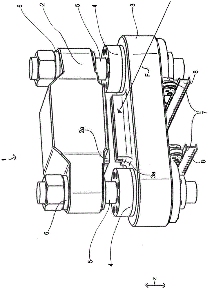
[0019] figure 1 The shearing machine 1 according to the invention is shown in perspective illustration. The shearing machine 1 includes an upper knife rest 2 and a lower knife rest 3 . An upper knife 2 a and a lower knife 3 a are installed at the upper knife rest 2 and the lower knife rest 3 . The upper knife rest 2 can move relative to the lower knife rest 3 . For this purpose, two hydraulic cylinders 4 are mounted on the lower tool carrier 3 , wherein corresponding piston rods 5 of the hydraulic cylinders 4 are connected to the upper tool carrier 2 . Through the control of the hydraulic cylinder 4, the upper tool rest 2 can move up and down relative to the lower tool rest 3, that is, along the figure 1 Movement in the direction of the arrow z shown in.
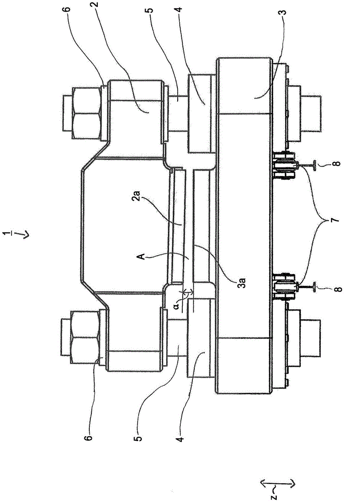
[0020] figure 2 Shown in side view from the front figure 1 The shearing machine1. This means that the lower tool holder 3 serves as a receiving element for the two hydraulic cylinders 4 . When the hydraulic cylinder...
PUM
 Abstract
Description
Claims
Application Information