

Implement for training facial muscle
A kind of exerciser and muscle technology, applied in the direction of muscle training equipment, gymnastics equipment, sports accessories, etc., can solve the user's discomfort, can not get the effect of facial muscle exercise, etc., to achieve the effect of effective exercise
- Summary
- Abstract
- Description
- Claims
- Application Information
AI Technical Summary
Problems solved by technology
Method used
Image

Examples
no. 1 Embodiment approach
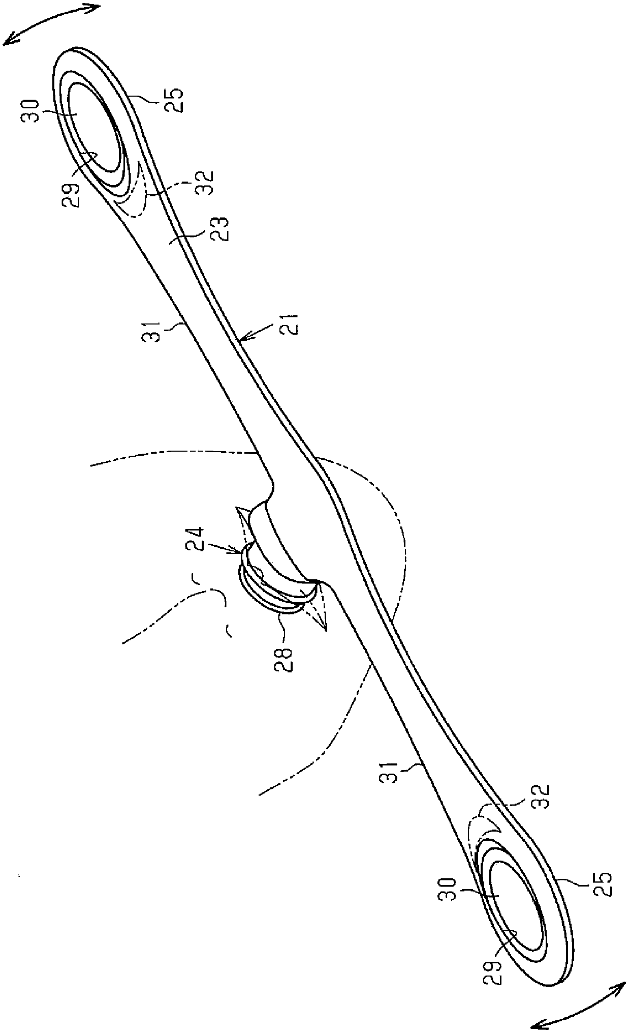
[0057] like figure 1 As shown, the facial muscle exerciser 21 of the first embodiment is held by the user with the mouth, and the user shakes the facial muscle exerciser up and down to exercise the user's orbicularis oris muscle and the cheeks connected to the orbicularis oris muscle. Facial muscles such as zygomaticus major, zygomaticus major and minor zygomaticus.
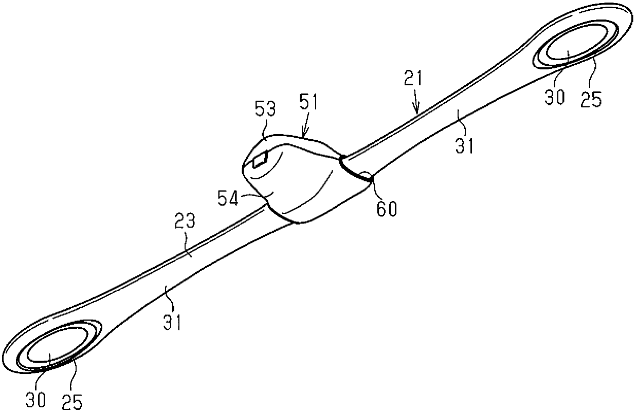
[0058] like image 3 , Figure 4 ,and Figure 8 As shown, the facial-muscle training apparatus 21 is provided with the elastic plate 22 in the shape of a linear strip formed by a leaf spring made of a steel plate. like Figure 9 and Figure 11 As shown, a core 27 formed of a hard resin such as polypropylene is fixed to the center portion in the longitudinal direction of the elastic plate 22 by molding using the elastic plate 22 as an insert. A protrusion 272 protruding from one end edge of the elastic plate 22 is formed on the core 27 . The mouthpiece 28 formed in a hollow shape is detachably attached to t...
no. 2 Embodiment approach
[0141] Hereinafter, the second embodiment of the present invention will be described focusing on the differences from the first embodiment. In addition, in the description of each embodiment and modification after this 2nd Embodiment, the part different from 1st Embodiment is mainly demonstrated.
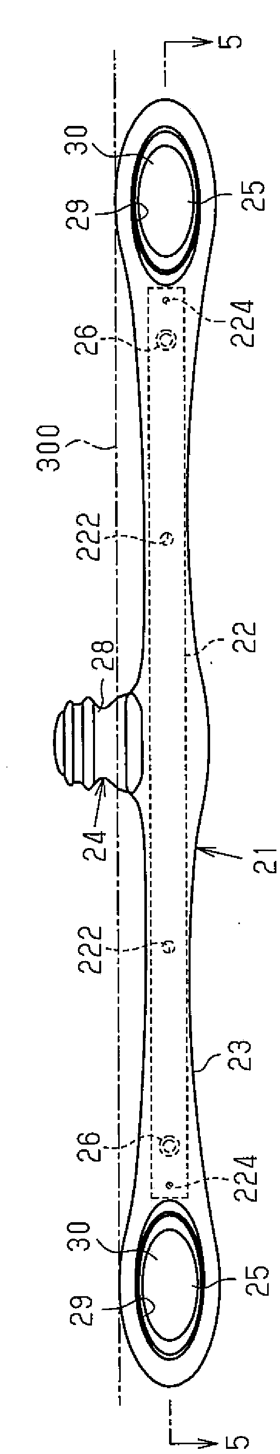
[0142] like Figure 19As shown, in this embodiment, the weight 30 in the above-described first real-time mode is omitted. In addition, large-area portions 122 are formed at both end portions of the elastic plate 22, and the large-area portions 122 are provided with a load function in place of the weight 30. In the case of this configuration, although not shown, the elastic plate 22 is provided with the through hole 222 and the bush 26 , and the bush 26 is preferably provided on the distal end of the large-area portion 122 .
[0143] In this embodiment, the number of parts is reduced, so that the configuration thereof is simplified. That is, since there is no heavy object provided...
no. 3 Embodiment approach
[0145] Next, based on Figure 20 and Figure 21 A third embodiment of the present invention will be described.
[0146] In the present embodiment, the protrusion 286 on the distal end side of the gripping portion 24 is provided in one place. The recessed portion 282 of the holding portion 24 includes a sloped surface 288 that reduces in diameter from the edge portion 285 to the circular arc portion 287 at the bottom, and a sloped surface 289 that gradually expands in diameter from the circular arc portion 287 to the distal end side of the holding portion 285 .
[0147] Therefore, in the present embodiment, the range of the recessed portion 282 in the protruding direction of the gripping portion 24 is widened, and the gripping position by the lips can be adjusted in the protruding direction. In addition, even if the gripping portion 24 is gripped in a single-arm state as in the first embodiment, since the gripping portion 24 is gripped by the user's lips at the recessed porti...
PUM
 Abstract
Description
Claims
Application Information