
A hinged part drilling jig
A drilling jig, hinged technology, used in drilling/drilling equipment, manufacturing tools, components of boring machines/drilling machines, etc., can solve problems such as drilling deep holes, and achieve the effect of ensuring accuracy and reducing wear and tear
- Summary
- Abstract
- Description
- Claims
- Application Information
AI Technical Summary
Problems solved by technology
Method used
Image

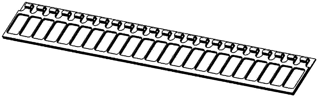
Examples
Embodiment Construction
[0013] The present invention will be described in detail below with reference to the drawings and embodiments.
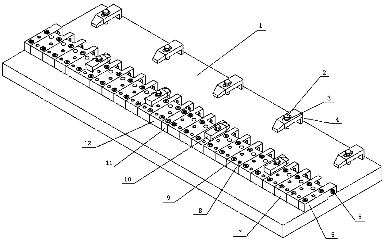
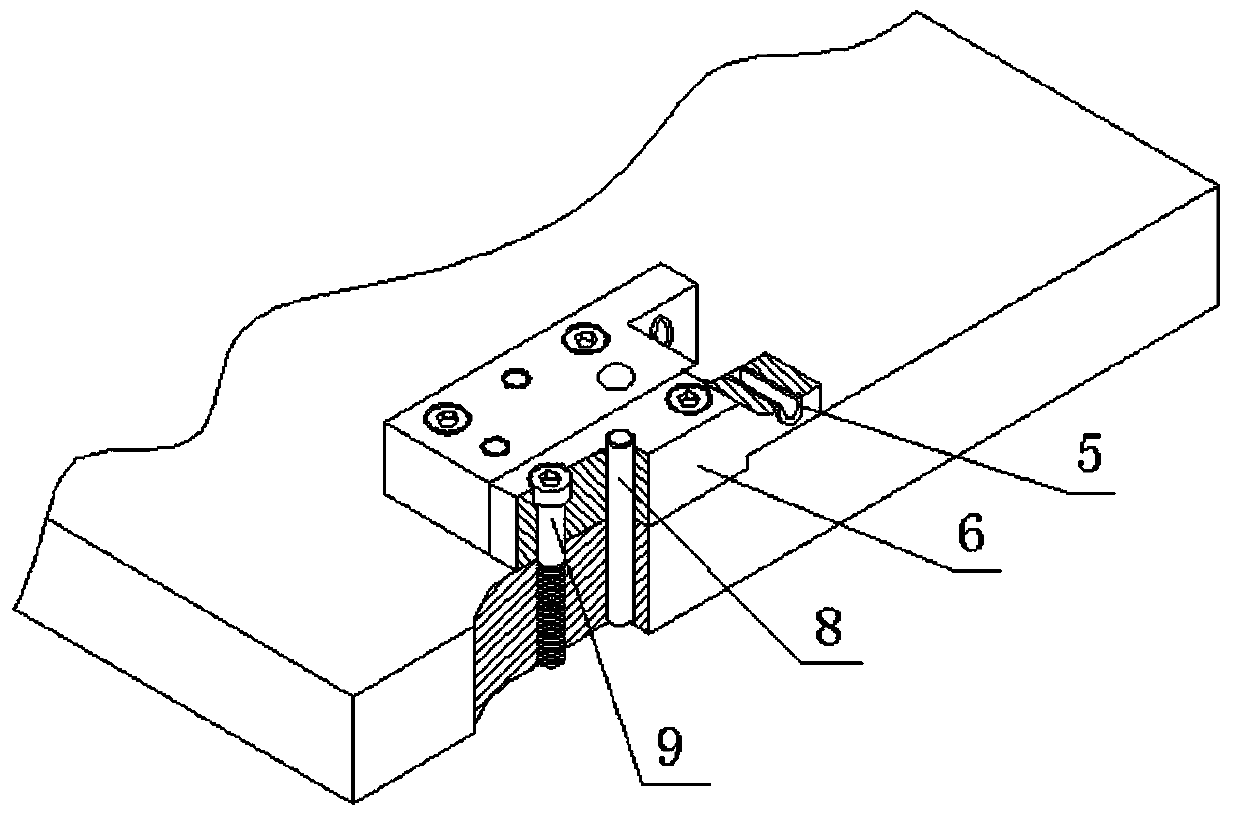
[0014] The present invention provides a hinge type parts drilling fixture, which includes: a support plate 1, a hexagonal head bolt 2, a gasket 3, a long pressing plate 4, a bushing 5, an end positioning block 6, a left-offset positioning block 7, Positioning pin 8, inner hexagonal bolt 9, short pressing plate 10, adjustment block 11, right-offset positioning block 12;
[0015] The upper surface of the support plate 1 is designed to be step-shaped, and the upper, lower and side surfaces of the step are finished, and the parallelism and straightness reach IT7 accuracy according to GB1800-79. The side surface of the step is the reference for installing the positioning block, so that the positioning hole of the positioning block can be located on a straight line.
[0016] A number of positioning blocks are installed on the support plate 1. The lower surface of the positionin...
PUM
 Abstract
Description
Claims
Application Information