
Dynamic and static ring structure of molded pulp rotating hub machine

A pulp molding, dynamic and static ring technology, applied in textiles and papermaking, etc., can solve the problems of easy plane wear, unstable air pressure, large fluctuations, etc., and achieve the effect of good sealing and quality assurance.

Active Publication Date: 2015-11-04
FOSHAN BESURE TECH
View PDF7 Cites 3 Cited by
  • Summary
  • Abstract
  • Description
  • Claims
  • Application Information

AI Technical Summary

Problems solved by technology

[0004] However, the air pressure in the actual production process is unstable and fluctuates greatly, which makes it difficult to control the spring preload
If the pre-pressure is too large, the friction of the sealing surface will be aggravated by the vacuum suction, and the plane is easy to wear, and the flatness after wear is out of tolerance, which will affect the sealing; is consumed, and affects the dehydration effect
In addition, due to the acid corrosion of the slurry, the spring usually fails prematurely, so that the moving ring and the static ring cannot be sealed

Method used


Image

  • Dynamic and static ring structure of molded pulp rotating hub machine
  • Dynamic and static ring structure of molded pulp rotating hub machine
  • Dynamic and static ring structure of molded pulp rotating hub machine

Examples


Embodiment Construction

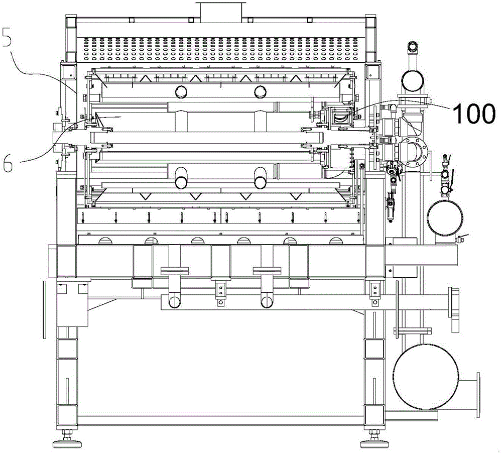
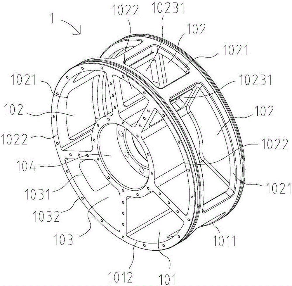
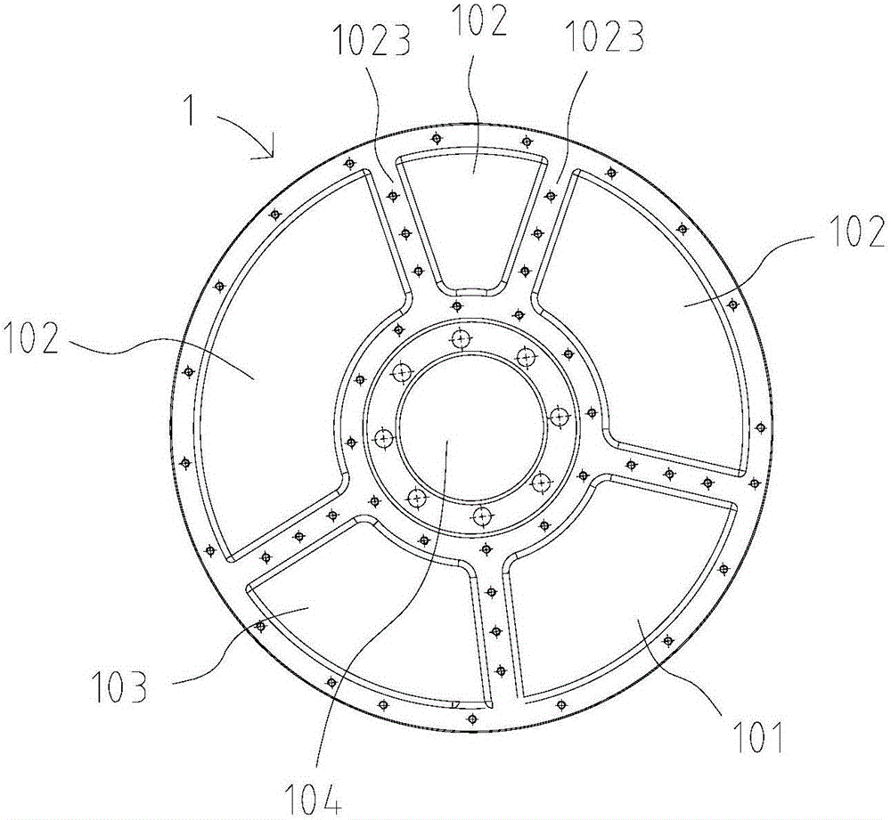
[0025] The technical scheme of the present invention is illustrated below in conjunction with accompanying drawing:

[0026] see Figure 2 to Figure 7 , the dynamic and static ring structure 100 of the pulp molding rotary hub machine of the present invention includes a dynamic ring body 2 and a static ring body 1, a first connecting shaft hole 104 is provided in the middle of the static ring body 1, and a first connecting shaft hole 104 is arranged in turn around the first connecting shaft hole 104. There are slurry suction air chamber 101, dehydration air chamber 102 and blowing air chamber 103, and the moving ring body 2 is provided with an air flow channel 202 and a second connecting shaft hole (not shown in the figure), and the moving ring body 2 can be opposite to the static ring The body 1 rotates, and the air flow channel 202 is switched to communicate with the above three air chambers in sequence; the static ring body 1 is columnar, and the slurry suction chamber 101, ...


PUM


Abstract

The invention discloses a dynamic and static ring structure of a molded pulp rotating hub machine. The dynamic and static ring structure comprises a dynamic ring and a static ring, the static ring is columnar, a pulp suction air chamber, a dehydration air chamber and a blowing air chamber are communicated with the outer side end face and peripheral side of the static ring, the dynamic ring is columnar, and is provided with a static ring containing cavity with an opening in the outer side end face, and the inner end of an airflow channel of the dynamic ring is communicated with the peripheral side of the static ring containing cavity. The outer side end face of the static ring is arranged in the static ring containing cavity outwards, the axial position of the airflow channel on the end opening of the static ring containing cavity corresponds to the axial position of an inlet of the pulp suction air chamber, the axial position of an inlet of the dehydration air chamber and the axial position of an outlet of the blowing air chamber, and a sealing structure is arranged between the peripheral side of the static ring and the peripheral side of the static ring containing cavity. Compared with the prior art, the dynamic ring and the static ring are of a columnar structure, sprig pressure sealing is replaced with the sealing structure between the peripheral side of the static ring and the peripheral side of the static ring containing cavity, the defects caused by a spring structure adopted in the prior art are avoided, and good sealing is achieved.

Description

technical field [0001] The invention belongs to the technical field of a pulp molding hub machine, and in particular relates to a dynamic and static ring structure of a pulp molding hub machine. Background technique [0002] The dynamic and static ring structure is a core technology used for vacuum suction forming of pulp molding rotary hub machine, dehydration of wet billet, and transfer of wet billet to the next drying process by air blowing. [0003] The moving ring in the prior art is a circular plate with evenly distributed air holes, the static ring is a cylinder, and there are slurry suction, dehydration and air blowing air chambers distributed around the circumference of the cylinder plane. The two planes of the moving ring and the static ring are vertically attached, the moving ring rotates inside the static ring, and the air holes of the moving ring pass through the different functions of each air chamber of the static ring to realize the above-mentioned production...

Claims


Application Information

Patent Timeline
Patent Type & Authority Applications(China)
IPC IPC(8): D21J5/00
Inventor 赵宝琳
Owner FOSHAN BESURE TECH
Learn More