Overpass enabling motor vehicles to be steered to wanted driving directions

A technology for overpasses and turning lanes, which is applied in the field of overpasses and turns, which can solve problems such as congestion, increased traffic flow, and prone to traffic accidents, and achieve the effects of reducing traffic flow, reducing traffic pressure, and reducing traffic hazards

Inactive Publication Date: 2015-11-04
梁真成
View PDF0 Cites 1 Cited by
  • Summary
  • Abstract
  • Description
  • Claims
  • Application Information

AI Technical Summary

Problems solved by technology

[0002] At present, the ring-shaped overpass requires a large number of lane changes to implement turns in all directions. Lane changes will bring traffic accidents, while the traditional butterfly-shaped overpass implements left and right by turning right. It is necessary to keep to the right to realize the turn, and the motor vehicle that has completed the turn needs to change lanes to the left to avoid turning again. For example, the straight road from south to north accepts the northbound road from the straight road from west to east to merge first, and then proceeds after the merge. Turn right to realize westward travel on the south-to-north straight road, turn right on the west-to-east straight road and merge into the south-north straight road to the south-to-north straight road, turn right and merge into the east-to-west merged road, from west to east Cars on the straight road wishing to go north must leave the merge on the left after merging into the south-to-north road, while cars on the south-to-north straight road wishing to travel west must enter this merge, and there are overlapping lane changes, which are prone to accidents traffic accident
The U-turn of the overpass needs to enter the steering system and complete two turns to realize the U-turn, which will increase the unnecessary flow of traffic and cause congestion

Method used


Image

  • Overpass enabling motor vehicles to be steered to wanted driving directions
  • Overpass enabling motor vehicles to be steered to wanted driving directions
  • Overpass enabling motor vehicles to be steered to wanted driving directions

Examples


Embodiment Construction

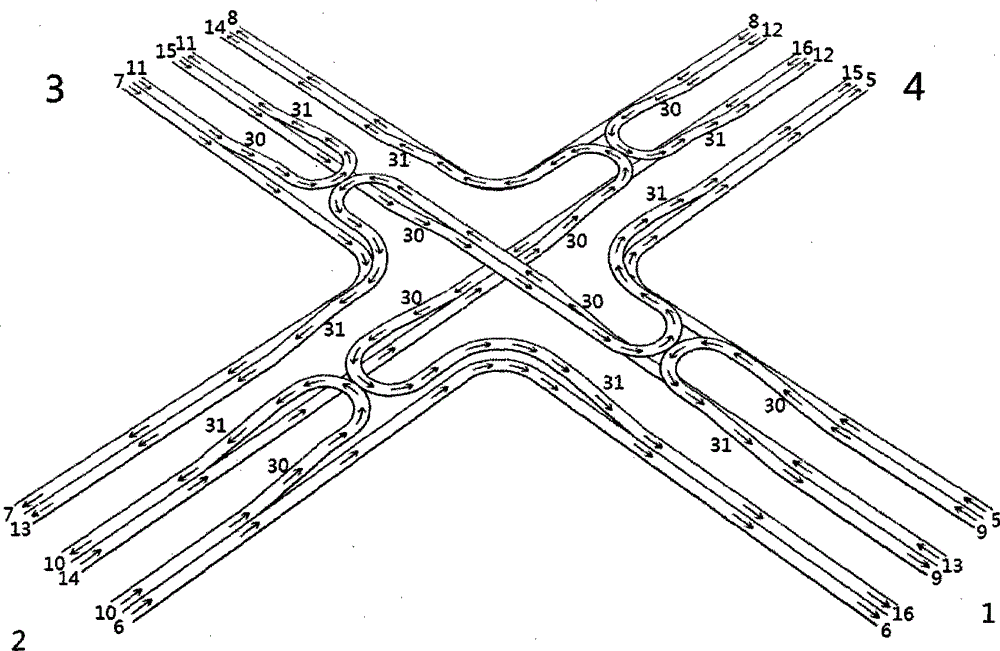
[0045] exist figure 1 Middle (2) is heading south, take the south as the starting direction and enter from the left-hand road (14), (13) and (15) form an elevated road with the straight road after passing through (30) uphill, and (14) proceeds after the elevated part (30) Go uphill, and then make an elevated 180-degree turn to the left. At this time, the direction facing is south. After a short straight road, turn 90 degrees to the right, go downhill through (31), and reach the west direction of (3) The (14) left-hand lane completes the section. At this time, the U-turn road (12) in the north direction of (4) passes through (30) and turns to the left 180 degrees elevated, and returns to the return part of the U-turn road (12) in the north direction of (4) through the downhill slope of (31). The 180-degree turn of the U-turn road and the 180-degree left turn of the left-hand road form two oppositely adjacent and opposite semi-circular figures.

[0046] exist figure 1 Middle ...


PUM


Abstract

The invention provides an overpass which enables motor vehicle drivers to steer motor vehicles to the wanted driving directions. The overpass is provided with a turning-round system in each direction without needing traffic lights. According to the overpass, a left-driving road is steered behind an overlapping part instead of being steered in the overlapping overhead part of a straight road, the left driving road is steered left by 180 degrees to become a semicircle with the direction opposite to the original driving direction after a height difference is caused by lifting the left driving road or lifting the straight road, the left driving road is opposite to a semicircular turning-round road which is also steered left by 180 degrees in an overhead mode without contacting after the semicircular turning-round road is lifted, and then the left driving road is steered right by 90 degrees and then enters the straight direction through descending to be steered left. According to the overpass, the motor vehicle drivers needing to steer the vehicles left can drive on the left, the motor vehicle drivers needing to steer the vehicles right can drive on the right, the motor vehicle drivers needing to go straight can drive in the middle, and road changing is not needed. The drivers can make preparations for turning round or steering the vehicles in advance, and the traffic lights are not needed.

Description

Technical field: [0001] The invention relates to the steering problem of an overpass, especially turning to the left when one wishes to travel to the left, and turning to the right when one wishes to travel to the right. technical background: [0002] At present, the ring-shaped overpass requires a large number of lane changes to implement turns in all directions. Lane changes will bring traffic accidents, while the traditional butterfly-shaped overpass implements left and right by turning right. It is necessary to keep to the right to realize the turn, and the motor vehicle that has completed the turn needs to change lanes to the left to avoid turning again. For example, the straight road from south to north accepts the northbound road from the straight road from west to east to merge first, and then proceeds after the merge. Turn right to realize westward travel on the south-to-north straight road, turn right on the west-to-east straight road and merge into the south-north...

Claims


Application Information

Patent Timeline
Patent Type & Authority Applications(China)
IPC IPC(8): E01C1/04
Inventor 梁真成
Owner 梁真成
Why Eureka
Try Eureka