Multi-beam TDMA satellite mobile communications system

a mobile communication system and multi-beam technology, applied in the field of satellite communication methods and apparatuses, can solve the problems of weak communication link between the terminal and any one satellite, inoperable link, loss of part of signal, etc., and achieve the effect of reducing error in received signal, and reducing blockage and fading

Inactive Publication Date: 2001-11-06
INMARSAT GLOBAL
View PDF28 Cites 96 Cited by
  • Summary
  • Abstract
  • Description
  • Claims
  • Application Information

AI Technical Summary

Benefits of technology

In this way, blockage may be reduced without the inherent disadvantages of CDMA.
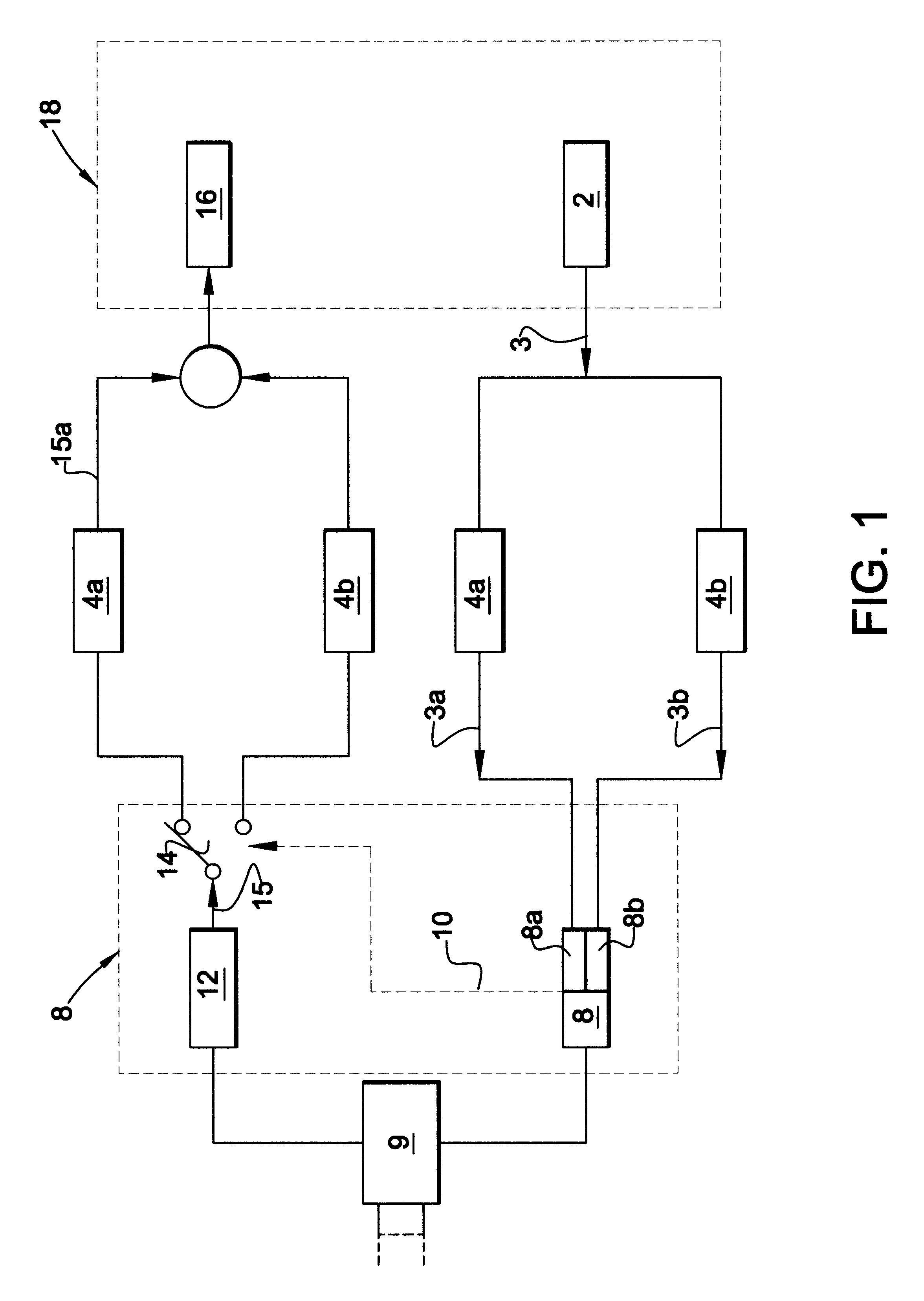
The terrestrial station may either decode the best received signal from each terminal or may combine all of the received signals to reduce error in the received signal. The terrestrial station may then select a forward link to each terminal through one or more of the satellites according to the quality of signal received from the terminal through the satellites.
Thus, a smooth handover may be achieved and blockage and fading may be reduced.
In order that the selection of satellite for the forward link may be transparent to the terminal, the terrestrial station may calculate the delay in the transmission via the selected satellite and adjust the timing of its transmission accordingly so that the transmitted signal is received by the terminal in the same time slot throughout the call. The calculation may take into account both the variation in delay as the selected satellite moves relative to the earth, and the difference in delay when handing over from one satellite to another, so that the quality of communication is not impaired by handover and complex circuitry is not required in the terminal.
In addition, the terrestrial station may compensate for the Doppler shift in the signal received from the terminal and adjust the frequency of the transmitted signal accordingly so that the terminal receives a signal at a constant frequency throughout a call. The Doppler shift may be partially compensated for by the satellites.
According to another aspect of the present invention, in order to facilitate simultaneous communication with multiple users through one satellite, areas of the earth are divided into a number of fixed regions, with a frequency being assigned to a terminal both for transmission and reception of signals according to the region in which the terminal is located. The locations of the regions are determined according to their positions on the earth, rather than their positions relative to the satellite. Simultaneous communication between different terminals in the same region and at the same frequencies may be achieved by allocating different time slots within a repeating time frame to each of the terminals. Since the different terminals using the same frequencies are contained within a fixed region and the variation in propagation delays is therefore limited, interference between the adjacent time slots is avoided.

Problems solved by technology

Thus, the communication link between the terminal and any one satellite may become weaker as the elevation angle of the satellite decreases and ultimately the link may become inoperable as the satellite moves out of sight of the terminal.
However, handover between satellites may result in loss of part of the signal, or sudden variations in signal quality, which are unacceptable in voice or data communications.
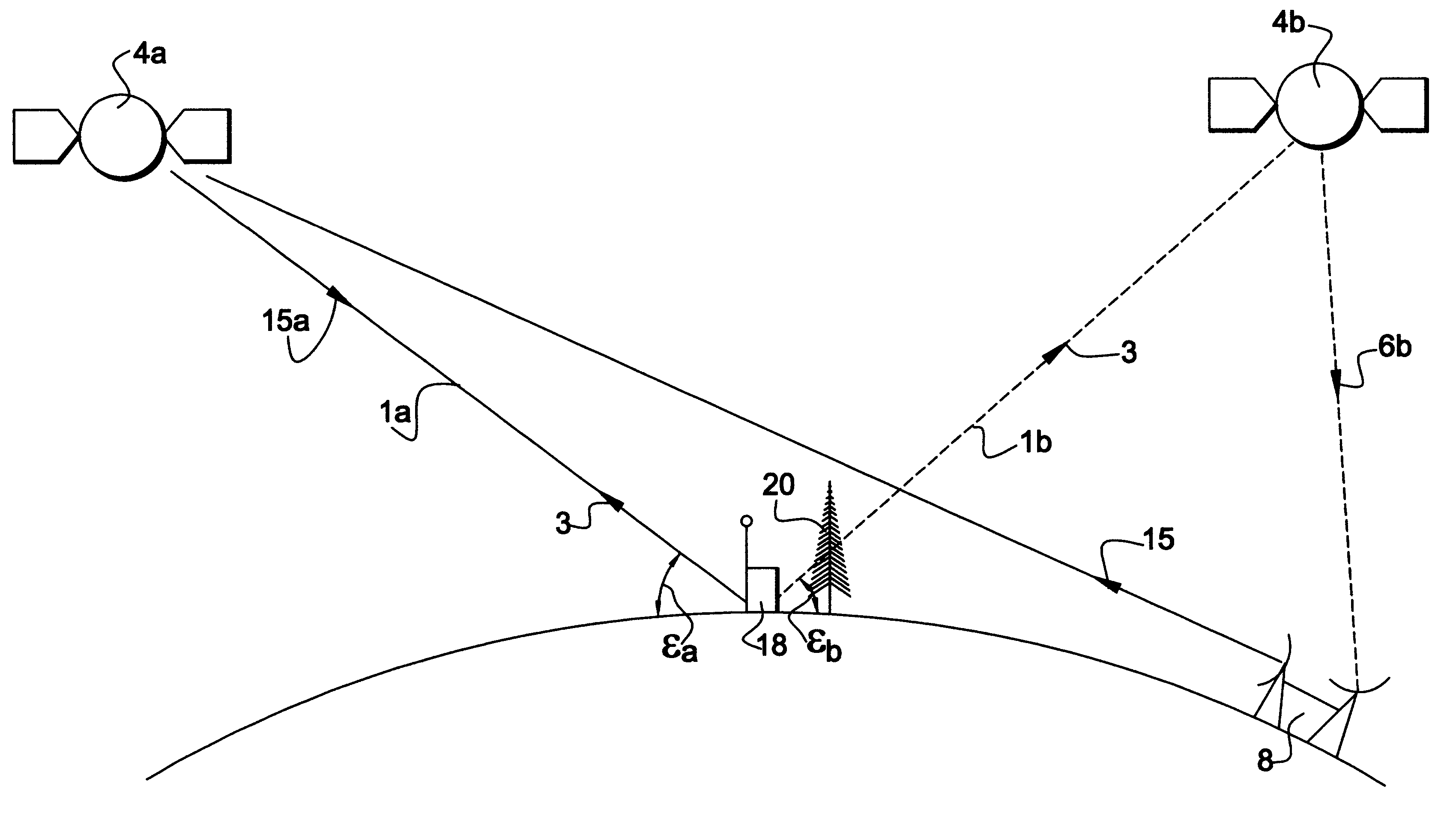
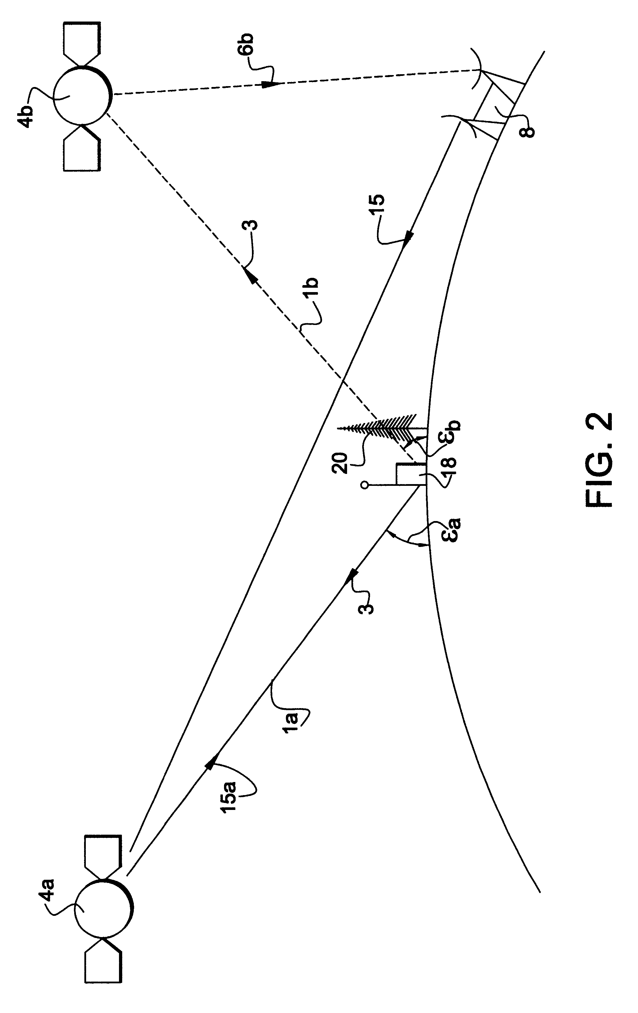
Furthermore, the line of sight between the terminal and a particular satellite may become obstructed by buildings, trees or other obstacles as the terminal or the satellite moves during a call.
This effect is known as "blockage", and leads to fading in the received signal.
The phase difference between the direct and reflected signals may lead to destructive interference at the terminal, so that the received signal strength is reduced.
However, CDMA suffers from a number of drawbacks when used for mobile communications.
The mobile terminals are complex, since they require a separate decoder for each satellite path.
Moreover, CDMA is inefficient in frequency re-use unless the users are evenly distributed, and power levels cannot be freely varied for each user without causing interference for other users.
Furthermore significant interference takes place at peak levels of use.

Method used


Image

  • Multi-beam TDMA satellite mobile communications system
  • Multi-beam TDMA satellite mobile communications system
  • Multi-beam TDMA satellite mobile communications system

Examples


first embodiment

A first embodiment of the present invention will now be described with reference to FIGS. 1 to 8.

In FIG. 1, a transmitter 2 of a mobile terminal transmits a signal 3. The mobile terminal has a substantially omni-directional antenna, so that the transmitted signal 3 is received by a first satellite 4a and a second satellite 4b in view of the mobile terminal. The signal 3 is retransmitted from each satellite 4a, 4b as separate signals 3a and 3b. These signals 3a and 3b are received by an earth station 8 having first and second receivers 8a and 8b for receiving signals from the first and second satellites 4a and 4b respectively. In this embodiment, the earth station 8 has first and second directional antennas directed towards the first and second satellites 4a, 4b respectively. Thus, the same information is received twice by the earth station 8 in the separate signals 3a and 3b. The earth station 8 may therefore select the better of the two signals 3a and 3b, e.g. the one with the lowe...

second embodiment

A second embodiment will now be described with reference to FIGS. 1 to 5, 10 and 11. The second embodiment differs from the first embodiment in the operation of the earth station 8, mobile terminal 18 and satellites 4, and in that the mobile terminal 18 receives signals from different satellites 4 in different time slots.

Signalling Format

As shown in FIG. 10, the mobile terminal 18 communicates with the earth station 8 during allocated time slots t within a repeating time frame T, via the first and second satellites 4a, 4b, or via first and second beams of one satellite, at pairs of frequencies f.sub.1, f.sub.1 ' and f.sub.2, f.sub.2 ' respectively.

In the example shown, the earth station 8 transmits a packet Rx.sub.1 in time slot t.sub.1 via the first satellite 4a, which packet is received at frequency f.sub.1 by the mobile terminal 18. The mobile terminal 18 then transmits a packet Tx.sub.1 in time slot t.sub.3 at the frequency f.sub.1 ' via a beam generated by the satellite 4a. The...


PUM


Abstract

An earth station receives a return signal via more than one satellite link from a mobile terminal using TDMA. The earth station selects one or more of the satellite links for transmitting a forward signal on the basis of the quality of signal received via each link. The earth section allocates frequency channels to the mobile terminals according to their location on the surface of the earth, so that the propagation time to and from those mobile terminals which share the same frequency channel is approximately the same. The satellite includes an antenna which generates an array of beams which are individually pointed to fixed regions of the earth, until the elevation of the satellite relative to a fixed region falls below a minimum value, in which case the corresponding beam is redirected to a new area, while the other beams remain pointed at the corresponding fixed areas. In this way, beam-to-beam handover is reduced, while maintaining the boresight of the antenna pointing at the nadir.

Description

TECHNICAL FIELDThe present invention relates to a method and apparatus for communication via satellite, and in particular but not exclusively for voice or data communication using non-geostationary satellites and / or mobile terminals.BACKGROUND ARTIn communication systems which use non-geostationary satellites, the number and orientation of satellites in view of a ground-based terminal varies during a call. Thus, the communication link between the terminal and any one satellite may become weaker as the elevation angle of the satellite decreases and ultimately the link may become inoperable as the satellite moves out of sight of the terminal. It is therefore desirable to select another satellite for communication with the terminal, in a procedure known as "handover". The document U.S. Pat. No. 3,349,398 describes one such method. However, handover between satellites may result in loss of part of the signal, or sudden variations in signal quality, which are unacceptable in voice or dat...

Claims


Application Information

Patent Timeline
Patent Type & Authority Patents(United States)
IPC IPC(8): H04B7/204H04B7/185
CPCH04B7/18534H04B7/18539H04B7/1855H04B7/2041
Inventor HART, NICHOLASBJORNSTROM, GUNNAR
Owner INMARSAT GLOBAL
Why Eureka
Try Eureka