Tactical ranging reticle for a projectile weapon aiming device

a projectile and aiming device technology, applied in the field of projectile weapon aiming systems, can solve the problems of difficult task, reticle often obstructing viewing in long ranges, and the resolution of mil-dot reticles cannot be sufficient for ranges exceeding 500 meters, so as to reduce visual obstruction and reduce visual obstruction

Inactive Publication Date: 2005-11-24
LEUPOLD & STEVENS
View PDF49 Cites 94 Cited by
  • Summary
  • Abstract
  • Description
  • Claims
  • Application Information

AI Technical Summary

Benefits of technology

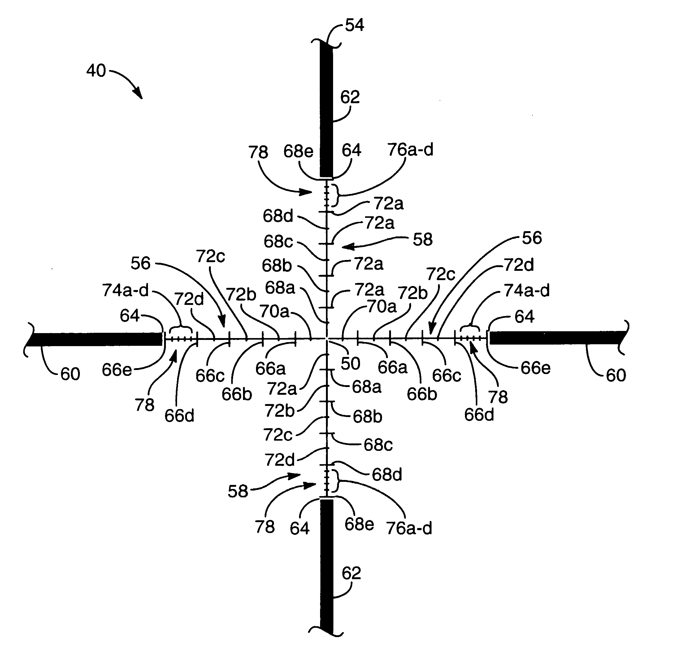
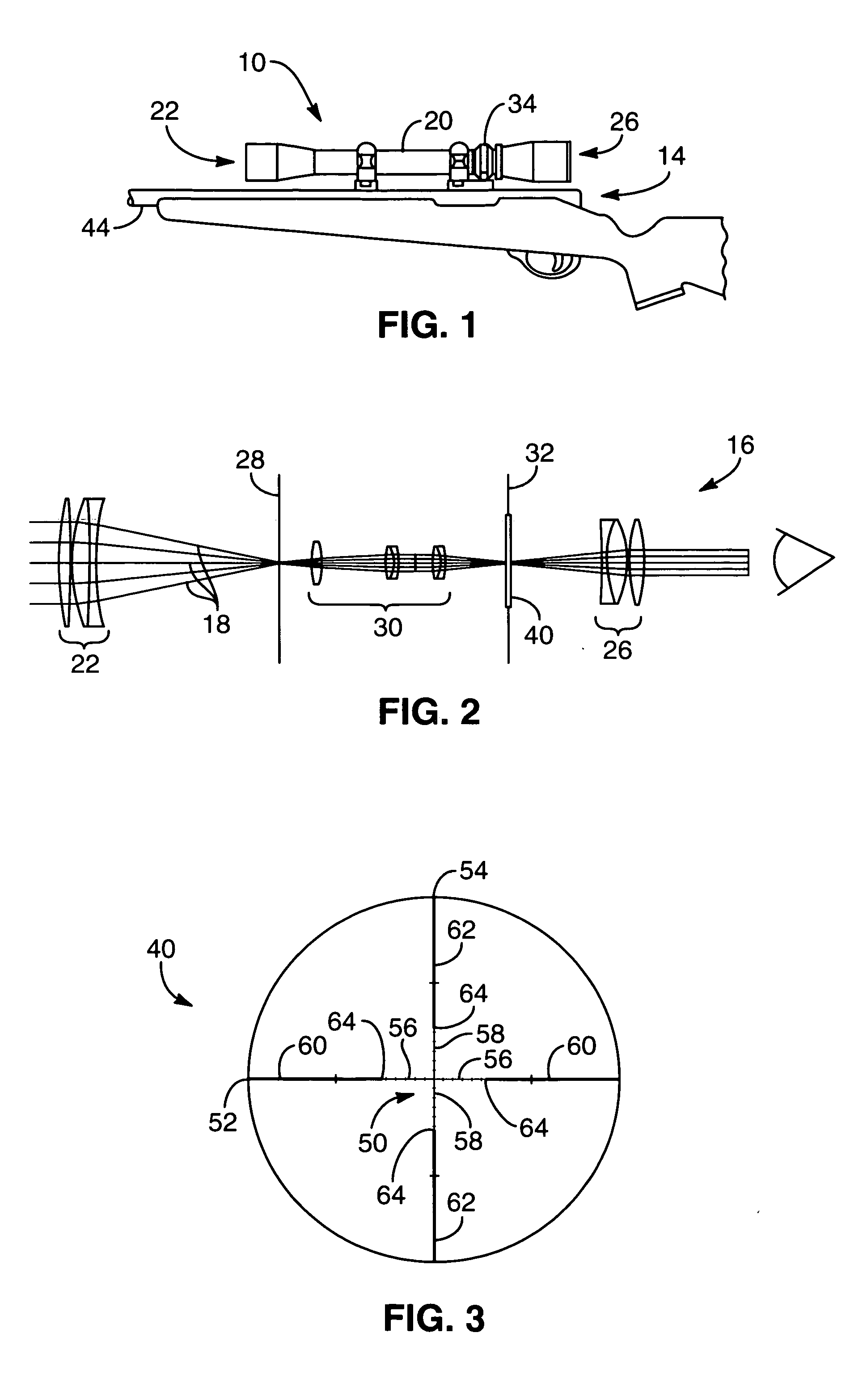
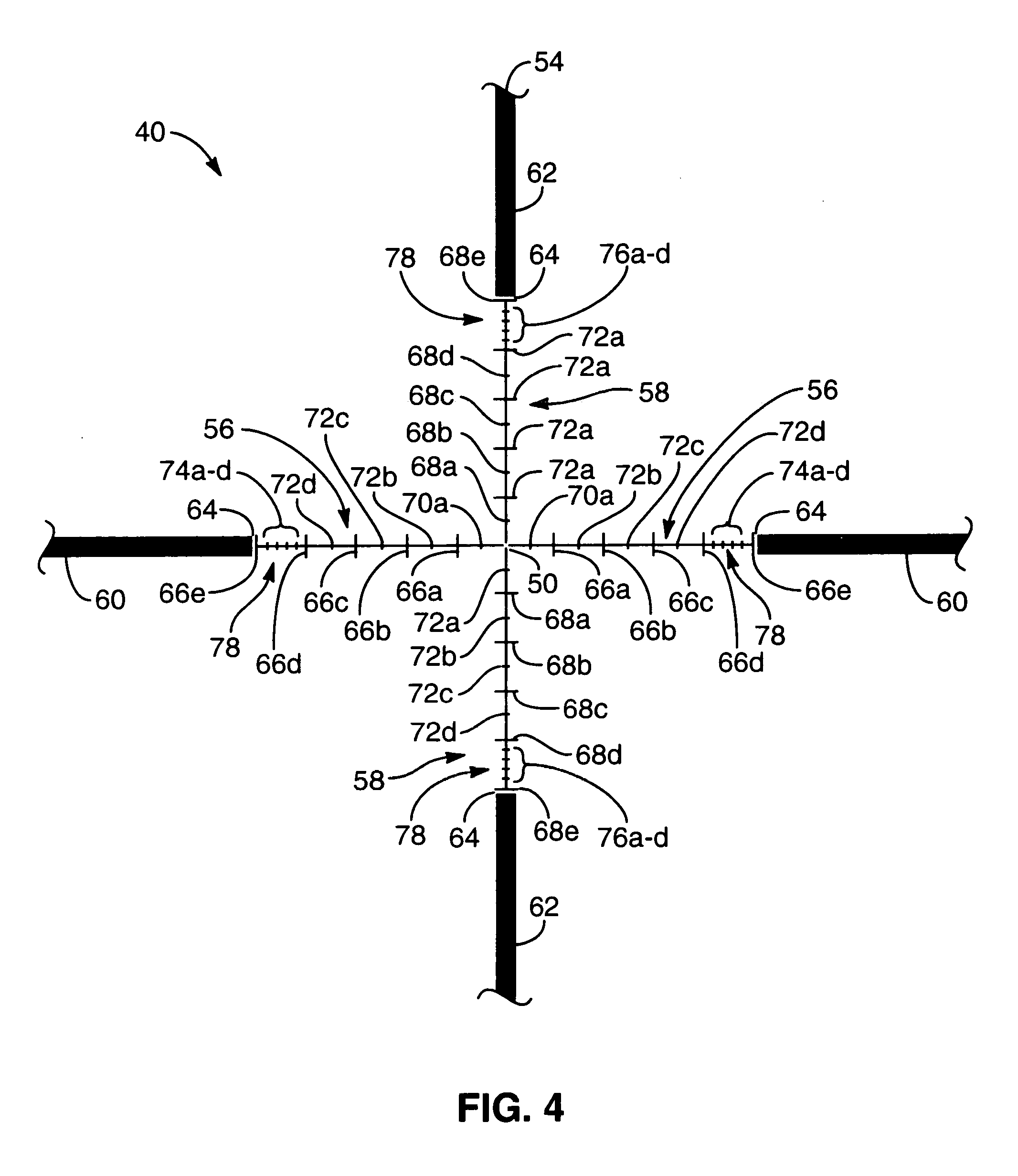
[0011] Secondary and tertiary marks are positioned on the sight lines to provide range finding and lead compensation for distances less than 500 meters. Tertiary marks may be disposed equidistantly between adjacent secondary marks to subdivide a unit of measure indicated by the secondary marks. Quaternary or long range marks are positioned on the sight lines and provide scale resolution for range finding and lead compensation at distances greater than 500 meters. The quaternary marks are positioned proximate to the post portions and remote from the primary aiming mark to reduce visual obstruction for short range targets. A plurality of quaternary marks may be disposed between a pair of secondary marks to indicate incremental units of measure. The secondary, tertiary, and quaternary aiming marks are further positioned to provide hold over compensation for ballistic drop at preselected incremental ranges for an elected group of cartridges. The secondary, tertiary, and quaternary aiming marks may have a thickness approximately equal to the central portions to reduce visual obstruction.

Problems solved by technology

A challenge in a long-range shooting environment is ranging a fairly small target at long distances.
This becomes a difficult task due to the lack of scale resolution and because the target is further away.
The round or football-shaped dots of a mil-dot reticle often obstruct viewing in long ranges.
Furthermore, as with other conventional reticles, the mil-dot reticle does not provide sufficient scale resolution for ranges exceeding 500 meters.
However, the rangefinders are separate from the crosshairs and cannot be used for ballistic drop compensation or for horizontal leading.

Method used


Image

  • Tactical ranging reticle for a projectile weapon aiming device
  • Tactical ranging reticle for a projectile weapon aiming device
  • Tactical ranging reticle for a projectile weapon aiming device

Examples


Embodiment Construction

[0020] Throughout the specification, reference to “one embodiment,”“an embodiment,” or “some embodiments” means that a particular described feature, structure, or characteristic is included in at least one embodiment. Thus appearances of the phrases “in one embodiment,”“in an embodiment,” or “in some embodiments” in various places throughout this specification are not necessarily all referring to the same embodiment. Furthermore, the described features, structures, or characteristics may be combined in any suitable manner in one or more embodiments.

[0021] Furthermore, the described features, structures, characteristics, and methods may be combined in any suitable manner in one or more embodiments. Those skilled in the art will recognize that the various embodiments can be practiced without one or more of the specific details or with other methods, components, materials, etc. In other instances, well-known structures, materials, or operations are not shown or not described in detail...


PUM


Abstract

A reticle of a projectile weapon aiming system such as a riflescope includes a primary aiming mark adapted to be sighted-in at a first selected range and further includes a plurality of secondary aiming marks spaced apart below the primary aiming mark. The secondary aiming marks are positioned to compensate for ballistic drop at preselected incremental ranges beyond the first selected range, for a selected group of ammunition having similar ballistic characteristics. Angles subtended by adjacent aiming marks of the reticle can be adjusted by changing the optical power of the riflescope, to thereby compensate for ballistic characteristics of different ammunition. In some embodiments, the reticle includes a set of windage aiming marks spaced apart along at least one secondary horizontal axis intersecting a selected one of the secondary aiming marks, to facilitate compensation for the effect of crosswinds on the trajectory of the projectile.

Description

RELATED APPLICATION [0001] This application claims the benefit under 35 U.S.C. § 119(e) of U.S. Provisional Patent Application No. 60 / 626,967, filed Nov. 10, 2004.COPYRIGHT NOTICE [0002]©2004 Leupold & Stevens, Inc. A portion of the disclosure of this patent document contains material which is subject to copyright protection. The copyright owner has no objection to the facsimile reproduction by anyone of the patent document or the patent disclosure, as it appears in the Patent and Trademark Office patent file or records, but otherwise reserves all copyright rights whatsoever. 37 CFR § 1.71(d). TECHNICAL FIELD [0003] This application relates to projectile weapon aiming systems such as riflescopes, to reticle configurations for projectile weapon aiming systems, and to associated methods of compensating for ballistic characteristics. BACKGROUND OF THE INVENTION [0004] Projectile weapon aiming systems are discussed herein principally with reference to their use on rifles and embodied in...

Claims


Application Information

Patent Timeline
Patent Type & Authority Applications(United States)
IPC IPC(8): F41G1/38
CPCF41G1/44F41G1/38
Inventor ZADEREY, SERGEY YURYEVANS-HENDRICK, ANDREWYORK, ANDREW W.
Owner LEUPOLD & STEVENS
Why Eureka
Try Eureka