Ribbed bar sleeve extrusion joint and connecting method

A technology of ribbed steel bars and extruded joints, applied in the processing of building materials, structural elements, building components, etc., to achieve the effects of ensuring safety, improving efficiency, and good connection quality

Inactive Publication Date: 2015-11-04
北京中睿创工程技术有限公司 +2
View PDF0 Cites 4 Cited by
  • Summary
  • Abstract
  • Description
  • Claims
  • Application Information

AI Technical Summary

Problems solved by technology

[0009] Based on the above-mentioned defects of the prior art, the present invention proposes a ribbed steel bar sleeve extrusion joint and connection method to solve the problem of mechanical connection of small-diameter steel bars, especially for one-time extrusion connection and to prevent extension and deformation of steel bars after extrusion question

Method used


Image

  • Ribbed bar sleeve extrusion joint and connecting method
  • Ribbed bar sleeve extrusion joint and connecting method
  • Ribbed bar sleeve extrusion joint and connecting method

Examples


Embodiment 1

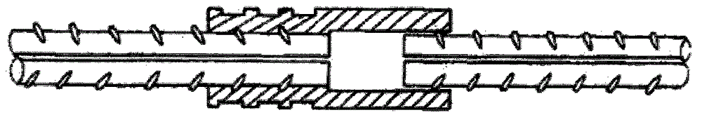
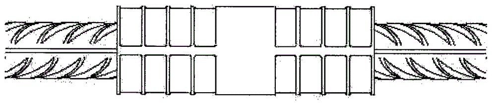
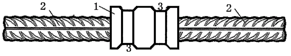
[0042] Such as Figure 3-6 As shown, a ribbed steel sleeve extrusion joint of the present invention includes a steel sleeve 1 and ribbed steel bars 2 at both ends, and the two ends of the steel sleeve 1 are connected to the ends of the ribbed steel bars 2 on both sides respectively. Set together. The extrusion joint of the present invention is formed by extruding the steel sleeve 1 covered with the ribbed steel bar 2 through extrusion tools and extrusion dies at one time, and the middle part of the steel sleeve 1 is provided with two symmetrical concave continuous extrusion rings 3, The central axis of the concave continuous extrusion ring 3 coincides with the axis of the steel sleeve 1, and the cross-sectional shape of the annular groove of the concave continuous extrusion ring 3 along the axial direction of the steel sleeve 1 (that is, the longitudinal section of the annular groove) is an isosceles inverted trapezoid, The cross-sectional shape of the concave continuous extr...

Embodiment 2

[0056] In another ribbed steel sleeve extrusion joint of the present invention, the cross-sectional shape of the annular groove of the concave continuous extrusion ring 3 along the axial direction of the steel sleeve 1 is rectangular (not shown in the figure, that is, the included angle is 90° case), other structures and connection methods are the same as in Embodiment 1, and will not be described in detail here.


PUM


Abstract

The invention relates to a ribbed bar sleeve extrusion joint and a connecting method. The ribbed bar sleeve extrusion joint comprises a steel sleeve and ribbed bars at two ends, wherein the two ends of the steel sleeve are respectively sleeved with the end parts of the ribbed bars at two sides, and the extrusion joint is formed by once extruding the steel sleeve with the ribbed bars by an extrusion tool and an extrusion die; two or four symmetrical concave continuous extrusion rings are arranged at the middle part of the steel sleeve, the central axis of the concave continuous extrusion rings is coincident with the axis of the steel sleeve, the ring groove section of the concave continuous extrusion rings along the axis direction of the steel sleeve is an isosceles inverted trapezoid or a rectangle, the cross section perpendicular to the axis direction of the steel sleeve is an oval, and an included angle between bevel edges at two sides of the isosceles inverted trapezoid and the axis direction of the steel sleeve is 60-90 degrees; the inner surface of the steel sleeve, on which the concave continuous extrusion rings are positioned, is closely occlusive with ribs on the surfaces of the two ribbed bars; and the diameter of each ribbed bar is 8-14mm.

Description

technical field [0001] The invention relates to a steel bar joint, in particular to a ribbed steel bar sleeve extrusion joint and a connection method, belonging to the technical field of steel bar mechanical connection. Background technique [0002] First of all, in the existing steel bar mechanical connection technology, the original ribbed steel bar sleeve extrusion connection, the size of the connected steel bar is basically in the range of 16-40mm, there is no small size, and the connection is multi-channel , multiple extrusions (see figure 1 ), and the steel bars at both ends are extruded separately, generally at least in 4 times and 4 times (two on one side). At the same time, there are many problems in the mechanical connection of small-diameter steel bars in prefabricated and prefabricated building structures. Since there is no ideal mechanical connection method, most of them use methods such as lap joints and binding. The solution to the mechanical connection of s...

Claims


Application Information

Patent Timeline
Patent Type & Authority Applications(China)
IPC IPC(8): E04C5/18E04G21/12
Inventor 白建平关宏伟
Owner 北京中睿创工程技术有限公司
Why Eureka
Try Eureka