Supercharge Your Innovation With Domain-Expert AI Agents!

Cement pipe

A cement pipe and pipe body technology applied to cement pipes. It can solve problems such as short service life and cracked cement pipes, and achieve the effect of prolonging service life and avoiding cracks

Inactive Publication Date: 2015-11-04
张芳
View PDF5 Cites 1 Cited by
  • Summary
  • Abstract
  • Description
  • Claims
  • Application Information

AI Technical Summary

Problems solved by technology

[0002] Cement pipes are widely used in urban groundwater systems. Sometimes the flow in the underground drainage system is very large, which creates a large pressure on the cement pipe wall. After a long time of use, the cement pipe will break and the service life will be short.

Method used


Image

  • Cement pipe

Examples


Embodiment Construction

[0012] The present invention will be described in detail below in conjunction with the accompanying drawings. The description in this part is only exemplary and explanatory, and should not have any limiting effect on the protection scope of the present invention.

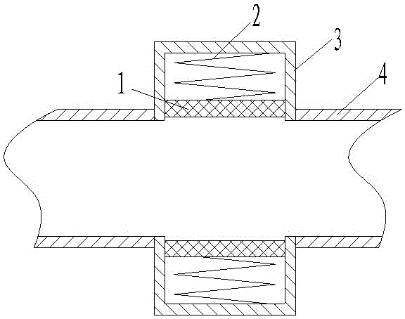
[0013] like figure 1 A cement pipe shown includes a pipe body 4 and a buffer tank 3,

[0014] The buffer tank 3 is arranged on the side of the pipe body 4 , a piston 1 is arranged in the buffer tank 3 , and a buffer spring 2 is arranged between the piston 1 and the bottom surface of the buffer tank 3 .

[0015] The cross section of the buffer tank 3 is circular.

[0016] The piston 1 is in sealing and sliding fit with the side wall of the buffer tank 3 .

[0017] Two buffer grooves 3 are arranged on the pipe body 4, and the notches of the two buffer grooves 3 are arranged opposite to each other.

[0018] The invention provides a cement pipe, which can buffer the pressure inside the cement pipe, prevent the cement...


PUM


Abstract

The invention discloses a cement pipe which comprises a pipe body and a buffer slot, wherein the buffer slot is formed in the side surface of the pipe body, a piston is arranged in the buffer slot, and a buffer spring is arranged between the piston and the bottom surface of the buffer slot. The pressure in the cement pipe can be buffered, the burst of the cement pipe is avoided, and the service life of the cement pipe is prolonged.

Description

technical field [0001] The invention relates to the technical field of building material manufacturing, in particular to a cement pipe. Background technique [0002] Cement pipes are widely used in urban groundwater systems. Sometimes the flow in the underground drainage system is very large, which creates a large pressure on the walls of the cement pipes. After a long period of use, the cement pipes will break and the service life will be short. Contents of the invention [0003] Aiming at the deficiencies of the prior art, the invention proposes a cement pipe, which can buffer the pressure inside the cement pipe, avoid the rupture of the cement pipe, and prolong the service life of the cement pipe. [0004] In order to achieve the above-mentioned purpose of the invention, the present invention provides the following technical solutions: [0005] A cement pipe, including a pipe body and a buffer tank, [0006] The buffer tank is arranged on the side of the pipe body, a ...

Claims


Application Information

Patent Timeline
IPC IPC(8): F16L9/08F16L57/02
CPCF16L9/08F16L57/02
Inventor 张芳
Owner 张芳
Features
  • R&D
  • Intellectual Property
  • Life Sciences
  • Materials
  • Tech Scout
  • Unparalleled Data Quality
  • Higher Quality Content
  • 60% Fewer Hallucinations
Learn More