Power factor measuring device

A measurement device and power factor technology, which is applied in the field of power factor measurement devices, can solve the problems of low utilization rate of equipment and large reactive power

Inactive Publication Date: 2015-11-04
NANJING PERLONG MEDICAL EQUIP
View PDF0 Cites 1 Cited by
  • Summary
  • Abstract
  • Description
  • Claims
  • Application Information

AI Technical Summary

Problems solved by technology

The lower the power factor, the smaller the average output power, the larger the reactive power of the circuit for alternating magnetic f

Method used


Image

  • Power factor measuring device

Examples


Embodiment Construction

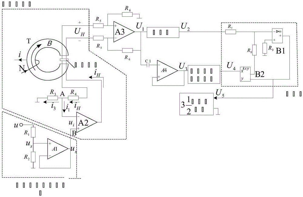
[0008] The present invention will be further described below in conjunction with the accompanying drawings.

[0009] refer to figure 1 , a power factor measuring device provided by the present invention includes a voltage input channel, a Hall multiplier connected to the voltage input channel, a third voltage amplifying device connected to the Hall multiplier, and a third voltage amplifying device connected to the voltage amplifying A filter connected to the output end of the device and an AC / DC conversion device, a divider connected to the filter and the AC / DC conversion device and a digital voltmeter connected to the divider, the voltage input channel includes a first voltage amplifier, The voltage input channel converts the AC voltage to be measured into a measurable voltage after passing through the first voltage amplifier, and the measurable voltage generates a first current after passing through the second voltage amplifier, and the first current and the current to be me...


PUM


Abstract

The invention discloses a power factor measuring device, which comprises a voltage input channel, a Hall multiplier connected with the voltage input channel, a third voltage amplifying device connected with the Hall multiplier, a filter and an AC DC conversion device connected with the output end of the voltage amplifying device, a divider connected with the filter and the AC DC conversion device and a digital voltmeter connected with the divider. The power factor measuring device of the invention has the advantage that a simple and reliable power factor measuring method which can carry out online monitoring continuously can be provided.

Description

technical field [0001] The invention belongs to the power factor measurement technology, in particular to a power factor measurement device. Background technique [0002] In an AC circuit, the power factor is a coefficient to measure the efficiency of electrical equipment. The invention can measure the power factor of the AC circuit. The device includes a voltage input channel, a Hall multiplier, a voltage amplification device, an AC-DC conversion device, a divider, And digital voltmeter, filter, etc. The power factor is defined as the cosine of the voltage and current phase difference Φ, represented by the symbol cosΦ, and the numerical representation is the ratio of active power to apparent power cosΦ=P / S. Power factor is an important technical data of power system. In the power system, generators or transformers have a rated capacity, and the average power they output depends on the load power factor, so the power factor is a coefficient to measure the efficiency of ele...

Claims


Application Information

Patent Timeline
IPC IPC(8): G01R21/08
Inventor 陈刚尹志嘉黄宝福胡利刚
Owner NANJING PERLONG MEDICAL EQUIP
Why Eureka
Try Eureka