Solar panel structure with pattern

A technology of solar panels and patterns, applied in photovoltaic power generation, electrical components, circuits, etc., can solve the problems of inability to form exquisite patterns and limited changes in appearance patterns, so as to achieve the effect of beautifying the appearance and environmental protection and energy efficiency

Inactive Publication Date: 2015-11-04
陈彩惠 +1
View PDF6 Cites 2 Cited by
  • Summary
  • Abstract
  • Description
  • Claims
  • Application Information

AI Technical Summary

Problems solved by technology

[0004] Please refer to figure 1 In the known solar panel structure shown, the general solar panel 10 only has a reflective substrate 13 with a circuit arrangement, and a layer of power generation layer 11 that provides power generation is arranged on the substrate 13. In order to protect the surface 111 of the power generation layer 11 from If it is damaged, it is known that the surface 111 will be covered with a layer of light-transmitting protective layer 12. Generally speaking, the protective layer 12 is mostly made of light-transmitting materials such as strengthened glass, but since the power generation layer 11 of the solar panel 10 is all The color is black, so the overall appearance of the solar panel 10 is uniformly black, resulting in the situation that the appearance composition that meets the use and the appearance design requirements often deviate from the situation, which is why solar panels are seldom used in the appearance area of ​​buildings. 10 main reasons for setting
[0005] Another known solar panel is a dye-sensitized solar panel (DDSC for short). Although it has the characteristics of colorfulness and light transmission, this technology is currently limited to the three primary colors of cyan, red and yellow. Although it can produce different colors, it belongs to a large area of ​​color blocks in appearance, and cannot form exquisite patterns, and the exquisite changes in appearance patterns can be produced quite limited.

Method used


Image

  • Solar panel structure with pattern
  • Solar panel structure with pattern
  • Solar panel structure with pattern

Examples


Embodiment Construction

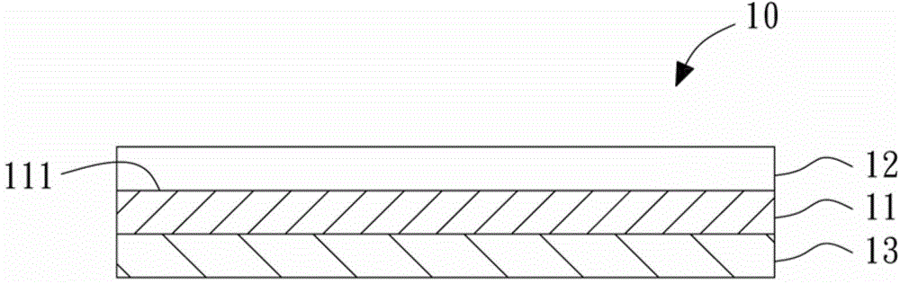
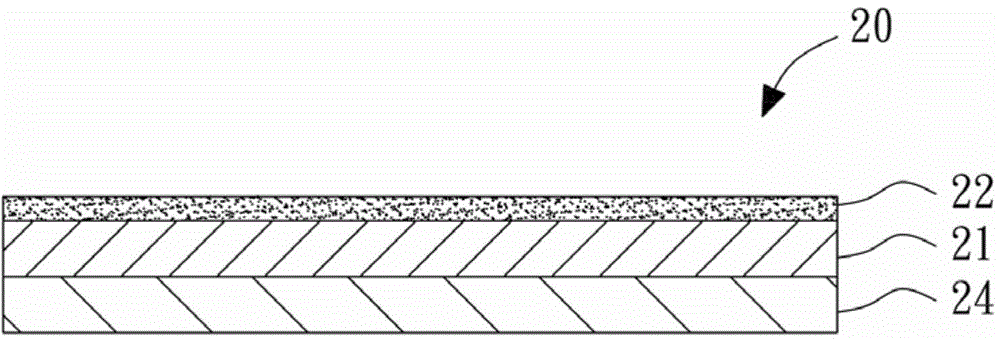
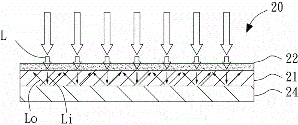
[0022] Please refer to figure 2 and image 3 As shown in the preferred embodiment of the present invention, compared with the known technology, the solar panel 20 of the present invention also has a substrate 24 and a power generation layer 21 arranged on the substrate 24, but it is not necessary to limit the composition of this structure, any transparent The following invention can be applied to any structure that generates electricity through the entry of light. The most important feature of the invention is that the surface of the power generation layer 21 is covered with a patterned light-transmitting layer 22. The patterned light-transmitting layer 22 is made of thin film or soft Light-transmitting materials, etc., and are coated on the power generation layer 21 under the requirement of a certain light transmittance by dyeing, coating or pasting colors to produce patterns, wherein the light transmittance refers to the light L penetrating The patterned transparent layer ...


PUM


Abstract

Disclosed is a patterned solar panel structure, comprising a substrate and a power generation layer; the surface of the power generation layer is covered with a patterned light transmission layer with specific light transmittance; the light transmitted through the patterned light transmission layer can still provide sufficient incident light or light reflected by the substrate to generate power in the power generation layer. With the generated power being controlled, the patterned light transmission layer of the solar panel structure can be designed as required by a designer. The solar panel structure not only generates power, but also has an aesthetic effect.

Description

technical field [0001] The invention relates to a patterned solar panel structure. In particular, it refers to a solar panel structure in which a light-transmitting layer with patterns or characters is coated on the surface of the solar panel, so as to generate electricity while having a beautiful appearance with patterns. Background technique [0002] In recent years, in order to be able to develop environmentally friendly energy, the use of solar panels has become one of the most mature and widely used technologies in the development of several green energy sources. However, the known solar panels must be installed outdoors in a location with sufficient sunlight in order to be able to use them. To achieve the preset power generation efficiency, however, in general metropolitan areas where the land use area is very expensive, if users want to install solar panels, most of them choose limited spaces such as houses or building roofs that are rarely used by people to install s...

Claims


Application Information

Patent Timeline
Patent Type & Authority Applications(China)
IPC IPC(8): H01L31/0216H01L31/0236H01L31/042
CPCH01L31/02H01L31/02167Y02E10/50
Inventor 陈彩惠李翠煌
Owner 陈彩惠
Why Eureka
Try Eureka