
Flexible foot structure of biped robot

A biped robot and flexible foot technology, applied in the field of robot foot structure and robot structure, can solve the problems affecting the performance and service life of robot actuators, affecting the stability of robot walking, and the size error of mechanical feet, so as to prevent forward and backward movement , Promote the rotation of the connecting rod, reduce the impact and stabilize the gait

Active Publication Date: 2020-03-27
ZHEJIANG UNIV
View PDF3 Cites 2 Cited by
  • Summary
  • Abstract
  • Description
  • Claims
  • Application Information

AI Technical Summary

Problems solved by technology

However, in actual use, due to the execution error of the robot actuator, or the structural size error of the mechanical foot, or the ground is non-planar, the mechanical foot will be deflected when it lands, causing one side of the mechanical foot to land first, rather than the entire mechanical foot. contact with the ground
In this state, there is a line contact between the mechanical foot and the ground, and the line contact form between the mechanical foot and the ground will last for a period of time. The momentary torque produces a large impact, which seriously affects the walking stability of the robot, and after the large impact is fed back to the mechanical foot, a large instantaneous current will be generated at the same time, which greatly affects the performance and service life of the robot actuator

Method used


Image

  • Flexible foot structure of biped robot
  • Flexible foot structure of biped robot
  • Flexible foot structure of biped robot

Examples


Embodiment Construction

[0034] In order to make the object, technical solution and advantages of the present invention clearer, the present invention will be further described in detail below in conjunction with the accompanying drawings and embodiments. It should be understood that the specific embodiments described here are only used to explain the present invention, not to limit the present invention.

[0035] In the description of the present invention, it should be understood that the orientation or positional relationship indicated by the terms "upper", "lower", "front", "rear", "inner", "outer" etc. Orientation or positional relationship is only for the convenience of describing the present invention and simplifying the description, and does not indicate or imply that the referred device or element must have a specific orientation, be constructed and operated in a specific orientation, and thus should not be construed as a limitation of the present invention.

[0036] In the description of the...


PUM


Abstract

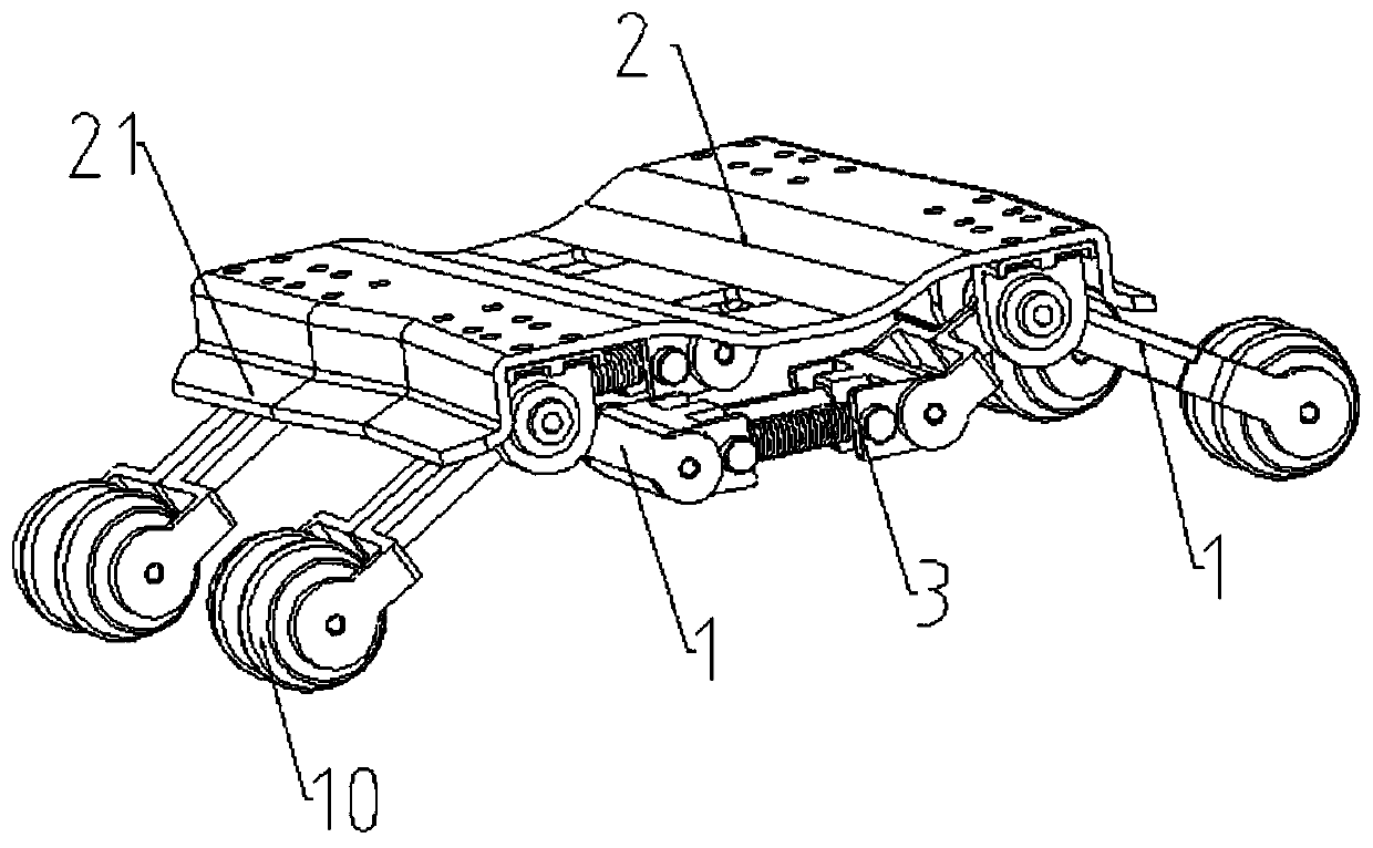
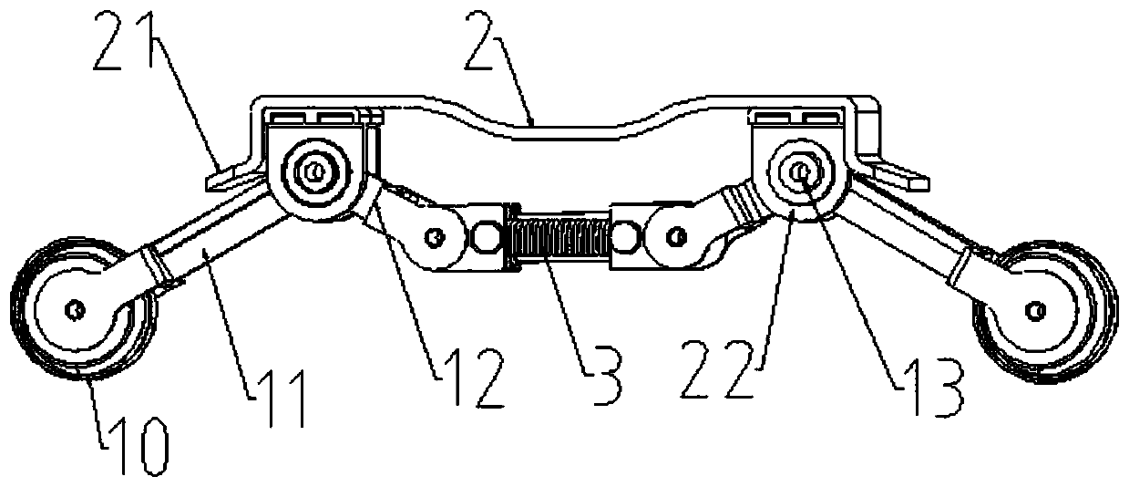
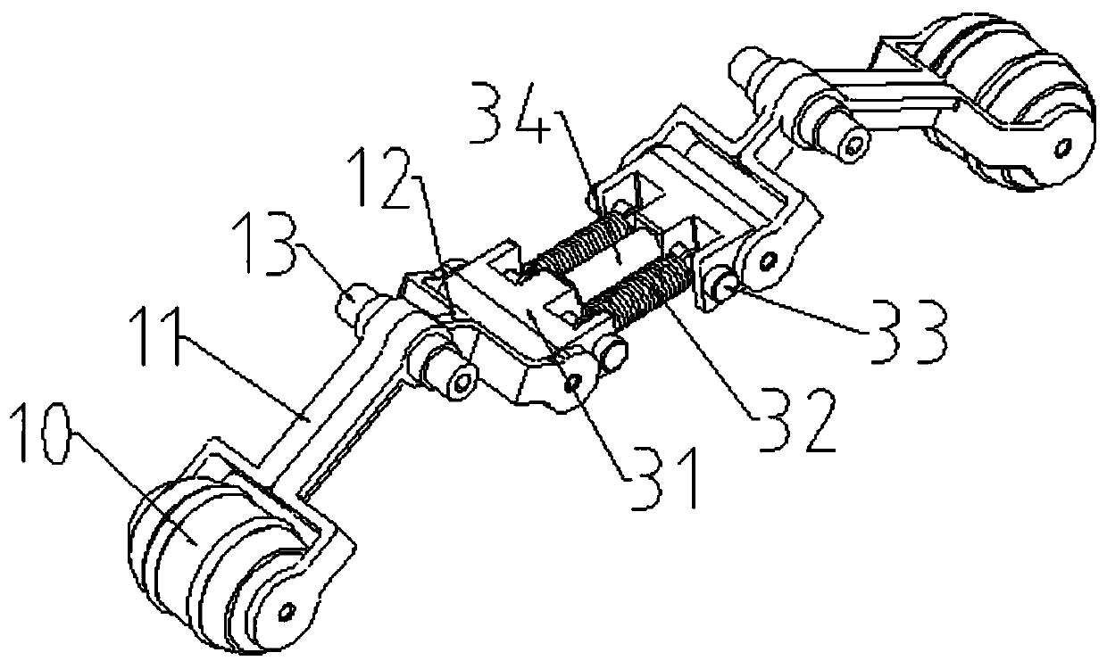
The invention provides a flexible foot structure of a biped robot. The device at least comprises a substrate and a supporting structure arranged on the lower side of the substrate, the supporting structure comprises two connecting rods and a telescopic elastic assembly, the connecting rods are hinged to the substrate, each connecting rod comprises a first supporting arm and a second supporting arm, the first supporting arms are fixedly connected with the second supporting arms, and the included angles between the first supporting arms and the second supporting arms are smaller than 180 degrees. The elastic assembly is hinged to the second supporting arms on the two sides. When the substrate is stressed to move downwards, the connecting rod is stressed to rotate, the second supporting arm is stressed to rotate, the second supporting arm drives the elastic assembly to be compressed or stretched in the rotating process, the elastic assembly provides buffering for rotation of the connecting rod in the stretching or compressing process, and the expansion buffering effect of the foot arch of the human foot is simulated. The robot has the function of simulating the foot arch of the humanfoot, the stress state of the human in the actual walking process is better met, and meanwhile the robot has higher stability in the walking simulating process.

Description

technical field [0001] The invention relates to the technical field of robot structure, especially the field of robot foot structure. Background technique [0002] Biomimetic robot is a hot topic in the field of modern mechanical research, and the foot structure of biomimetic robot is the key research object in biomimetic robot. In the prior art, the foot structure of the bionic robot is usually in the form of a flat plate, and the cushioning function of the foot is generally realized by setting a cushioning structure at the ankle joint or leg of the robot. However, the actual human foot includes the arch. When walking, the entire human foot skeleton is not completely attached to the ground, but the front and rear ends of the arch provide the main force, and the arch can be slightly expanded when the foot is fully loaded. , so as to play the effect of cushioning and shock absorption. Existing flat mechanical feet ignore the characteristic of the arch of the foot, or only i...

Claims


Application Information

Patent Timeline
Patent Type & Authority Applications(China)
IPC IPC(8): B62D57/028
CPCB62D57/028
Inventor 甘春标能一鸣葛一敏叶靖袁璐王小莹李子静
Owner ZHEJIANG UNIV
Learn More