
Flashlight and handle structure thereof

A handle and flashlight technology, which is applied in the field of flashlight and its handle structure, can solve the problems of not having the limit function of the battery cover assembly and the lamp head assembly, and the falling off of the battery cover assembly and the lamp head assembly, so as to achieve convenient lamp assembly, easy installation or disassembly , the effect of preventing shedding

Active Publication Date: 2014-04-09
SHENZHEN OCEANS KING LIGHTING ENG CO LTD +1
View PDF5 Cites 2 Cited by
  • Summary
  • Abstract
  • Description
  • Claims
  • Application Information

AI Technical Summary

Problems solved by technology

[0003] However, the handle of the current LED flashlight only has a carrying function, and does not have the function of limiting the battery cover assembly and the lamp cap assembly. The battery cover assembly and the lamp cap assembly of the current LED flashlight are easy to fall off from the lamp tube.

Method used


Image

  • Flashlight and handle structure thereof
  • Flashlight and handle structure thereof
  • Flashlight and handle structure thereof

Examples


Embodiment Construction

[0036] In order to facilitate the understanding of the present invention, the present invention will be described more fully below with reference to the associated drawings. Preferred embodiments of the invention are shown in the accompanying drawings. However, the present invention can be embodied in many different forms and is not limited to the embodiments described herein. On the contrary, these embodiments are provided to make the understanding of the disclosure of the present invention more thorough and comprehensive.

[0037] It should be noted that when an element is referred to as being “fixed” to another element, it can be directly on the other element or there can also be an intervening element. When an element is referred to as being "connected to" another element, it can be directly connected to the other element or intervening elements may also be present. The terms "vertical," "horizontal," "left," "right," and similar expressions are used herein for purposes ...


PUM


Abstract

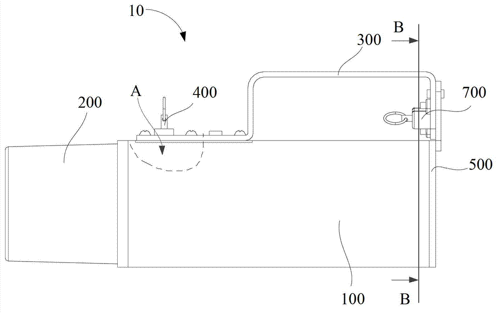
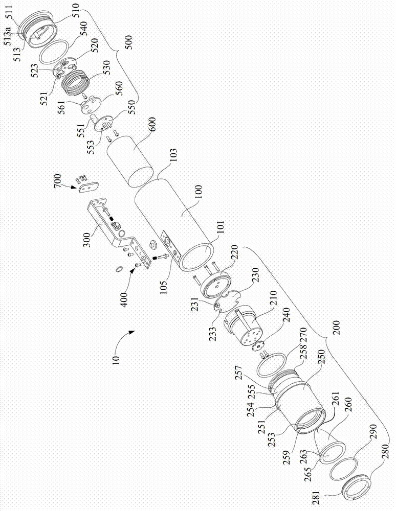
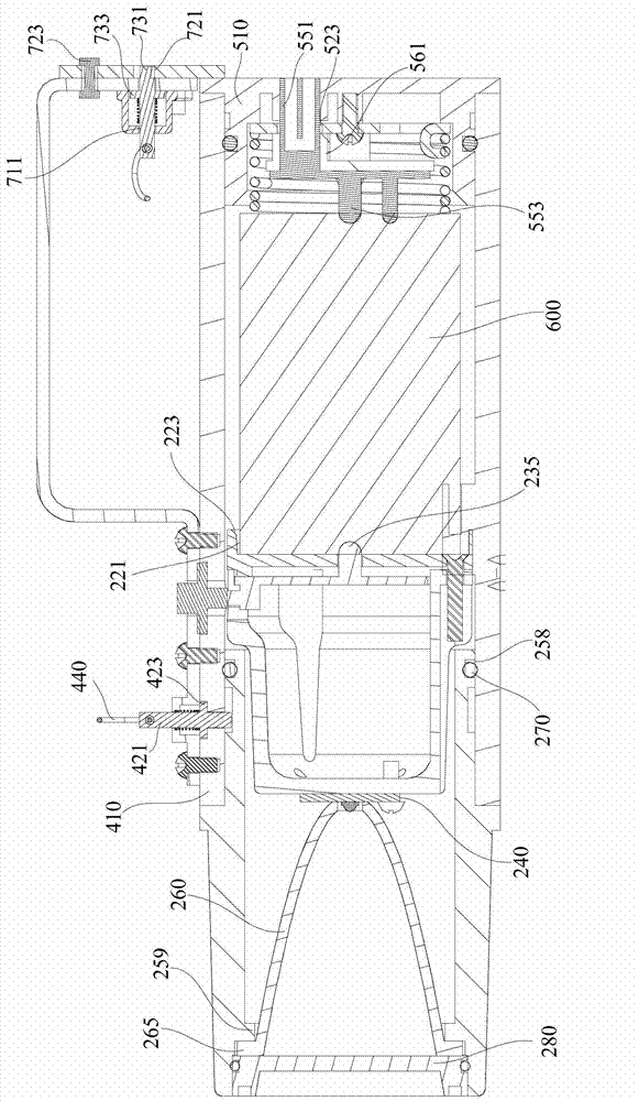
Disclosed are a flashlight and a handle structure thereof. The handle structure is used for limiting a lamp holder unit and a battery cover unit on a barrel. The lamp holder unit comprises a transparent cover provided with a limit groove. The battery cover unit comprises a tail cover. The handle structure comprises a handle, a lamp holder limiting unit and a lamp cover limiting unit. The lamp holder limiting unit arranged at one end of the handle comprises a first limit cover, a first limit pin, and a first return elastic member; the first limit pin penetrates the first limit cover and the barrel; the first return elastic member sleeves a first shank and abuts between a first retaining part of the first shank and the first limit cover. The battery cover limiting unit arranged at the other end of the handle comprises a second limit cover, a limit plate, a second limit pin and a second return elastic member; the limit plate is rotatably connected with the handle and abutted to the bottom of the tail cover; the limit plate is provided with a limit part; the second limit pin penetrates the second limit cover and the handle; the second return elastic member sleeves a second shank. The handle structure has the functions of lifting and preventing the battery cover unit and the lamp holder unit from dropping off.

Description

【Technical field】 [0001] The invention relates to a portable lighting tool, in particular to a torch and its handle structure. 【Background technique】 [0002] Flashlight is a common lighting tool in people's daily life. The first-generation torch is the first-generation torch, commonly known as "old-fashioned torch", with the shell of iron sheet plated on the surface. The bulb generally uses a tungsten filament incandescent bulb, which has low luminous efficiency, short service life, and is easy to be burned out. The battery uses a large alkaline battery, which has a large volume but low battery life. The shell of the flashlight is made of iron plated on the surface, which is light in weight but simple in craftsmanship. The flashlight with aluminum alloy as the shell material is the second generation flashlight, which has a new breakthrough in both performance and appearance. A typical representative of the second-generation torch is the use of krypton bulbs and alkaline ...

Claims


Application Information

Patent Timeline
Patent Type & Authority Applications(China)
IPC IPC(8): F21V21/40F21Y101/02F21Y115/10
Inventor 周明杰陈超
Owner SHENZHEN OCEANS KING LIGHTING ENG CO LTD
Learn More