A proximity sensor adjusting method and apparatus

A proximity sensor, intensity value technology, applied in the computer field, can solve the problem of whether the user's face is close to the proximity sensor and misjudged.

Active Publication Date: 2015-11-04
GUANGDONG OPPO MOBILE TELECOMM CORP LTD
View PDF5 Cites 31 Cited by
  • Summary
  • Abstract
  • Description
  • Claims
  • Application Information

AI Technical Summary

Problems solved by technology

[0006] Embodiments of the present invention provide a proximity sensor adjustment method and device to solve the pr

Method used


Image

  • A proximity sensor adjusting method and apparatus
  • A proximity sensor adjusting method and apparatus
  • A proximity sensor adjusting method and apparatus

Examples


Embodiment 1

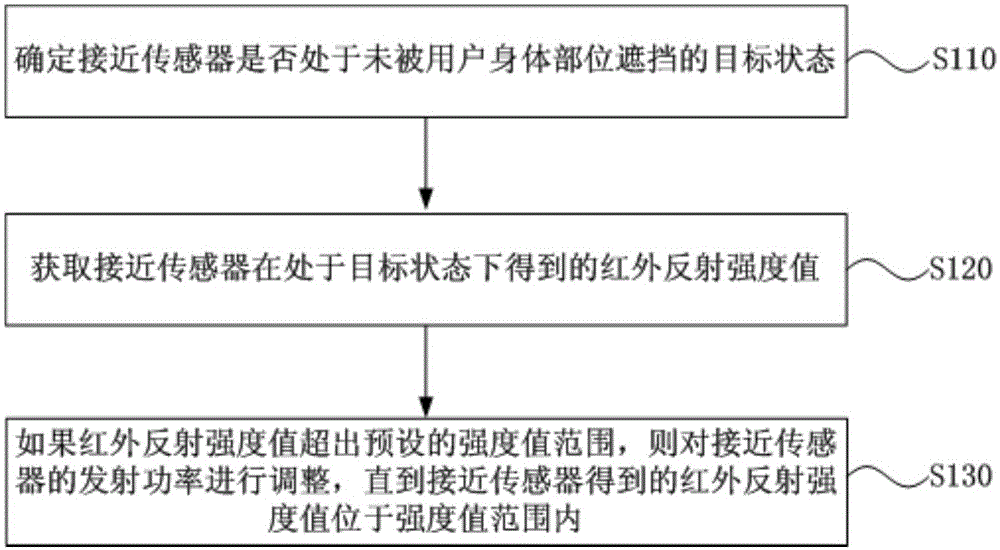
[0040] figure 1 It is a schematic flowchart of a method for adjusting a proximity sensor provided in Embodiment 1 of the present invention. The method can be performed by a proximity sensor regulated device, implemented by software and / or hardware, which can be built into a terminal such as a smartphone, tablet, laptop, desktop or personal digital assistant. Wherein, the terminal is equipped with a proximity sensor, and can detect whether the user's face approaches the proximity sensor according to the infrared reflection intensity value obtained by the proximity sensor. see figure 1 The method for adjusting the proximity sensor provided in this embodiment specifically includes the following steps:

[0041] Step S110, determining whether the proximity sensor is in a target state that is not blocked by the user's body parts;

[0042] Step S120, acquiring the infrared reflection intensity value obtained by the proximity sensor in the target state;

[0043] Step S130, if the ...

Embodiment 2

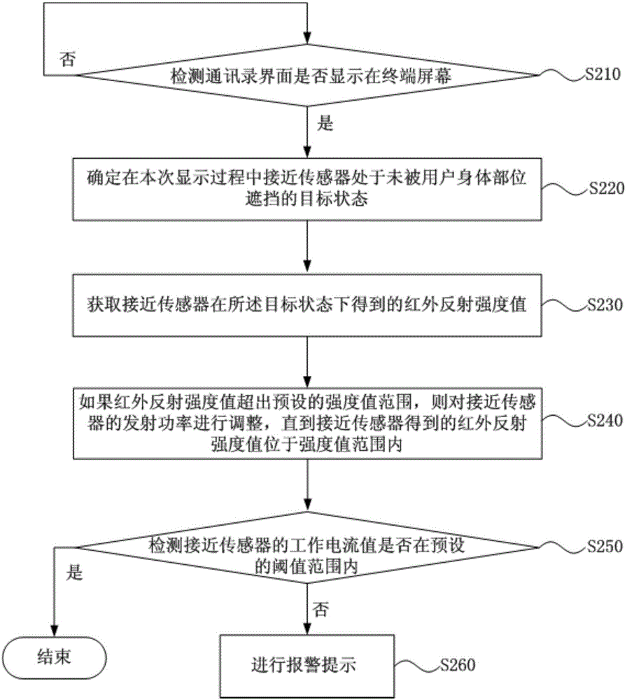
[0053] figure 2 It is a schematic flowchart of a method for adjusting a proximity sensor provided in Embodiment 2 of the present invention. This embodiment provides a preferred embodiment on the basis of the first embodiment above, to further optimize the step of "identifying whether the terminal where the proximity sensor is located is not in a call state" in the example of the first embodiment, and add an alarm detection step. see figure 2 The method for adjusting the proximity sensor provided in this embodiment specifically includes the following steps S210-S260.

[0054] Step S210, detecting whether the address book interface is displayed on the terminal screen.

[0055] If yes, execute step 220; otherwise, continue to execute step S210.

[0056] Step S220, determining that the proximity sensor is in a target state where the proximity sensor is not blocked by the user's body parts during this display process. Execute step 230 .

[0057] Step S230, acquiring the infr...

Embodiment 3

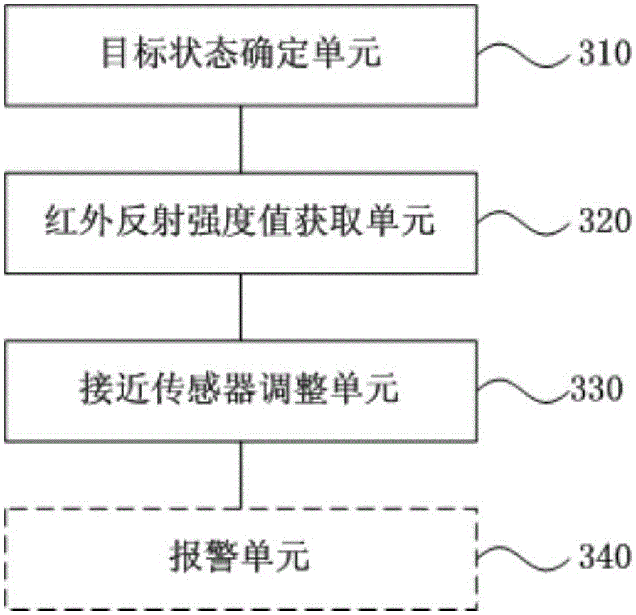
[0066] image 3 It is a schematic structural diagram of the device for adjusting the proximity sensor provided by Embodiment 3 of the present invention. see image 3 , the specific structure of the device is as follows:

[0067] A target state determining unit 310, configured to determine whether the proximity sensor is in a target state that is not blocked by a user's body part;

[0068] An infrared reflection intensity value acquisition unit 320, configured to acquire an infrared reflection intensity value obtained by the proximity sensor when the proximity sensor is in the target state;

[0069] The proximity sensor adjustment unit 330 is configured to adjust the transmission power of the proximity sensor until the infrared reflection intensity value obtained by the proximity sensor is within the range of the intensity value if the infrared reflection intensity value exceeds the preset intensity value range. value range.

[0070] Exemplarily, the target state determinin...


PUM


Abstract

The embodiment of the invention discloses a proximity sensor adjusting method and apparatus. The method comprises the steps of determining whether a proximity sensor is in a target state of not being shielded by a body part of a user; when the proximity sensor is in the target state, obtaining an infrared reflection intensity value obtained by the proximity sensor; and if the infrared reflection intensity value exceeds a preset range of intensity values, adjusting of emission power of the proximity sensor is carried out until the infrared reflection intensity value obtained by the proximity sensor is positioned in the range of intensity values. According to the technical scheme provided by the embodiment, problems of misjudgment of whether the face of the user is close to the proximity sensor are solved.

Description

technical field [0001] The embodiments of the present invention relate to the field of computer technology, and in particular to a method and a device for adjusting a proximity sensor. Background technique [0002] Proximity sensors are widely used in smartphones. When the user makes a call on the mobile phone and the face is close to the proximity sensor located under the touch screen layer of the mobile phone, the mobile phone screen is turned off to reduce power consumption and reduce touch screen misoperation; when the user hangs up the phone and moves away from the proximity sensor, the mobile phone screen lights up . [0003] The proximity sensor is built with an infrared generating tube and an infrared receiving tube. When the user's face approaches or moves away from the proximity sensor, the infrared receiving tube will receive infrared reflection signals of different intensity, and convert the strength of the signal into a corresponding infrared reflection intens...

Claims


Application Information

Patent Timeline
IPC IPC(8): H04M1/725
Inventor 张强
Owner GUANGDONG OPPO MOBILE TELECOMM CORP LTD
Why Eureka
Try Eureka