
neck massager

A massager and neck technology, applied in the field of massager, can solve problems such as massage inconvenience

Active Publication Date: 2018-02-27
SHENZHEN BREO TECH CO LTD
View PDF10 Cites 0 Cited by
  • Summary
  • Abstract
  • Description
  • Claims
  • Application Information

AI Technical Summary

Problems solved by technology

[0003] The purpose of the present invention is to provide a neck massager, aiming to solve the problem of inconvenient massage caused by the need for both hands to assist the neck massager in the prior art

Method used


Image

  • neck massager
  • neck massager
  • neck massager

Examples


Embodiment 1

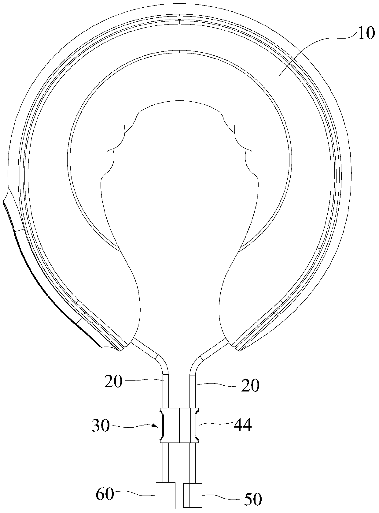
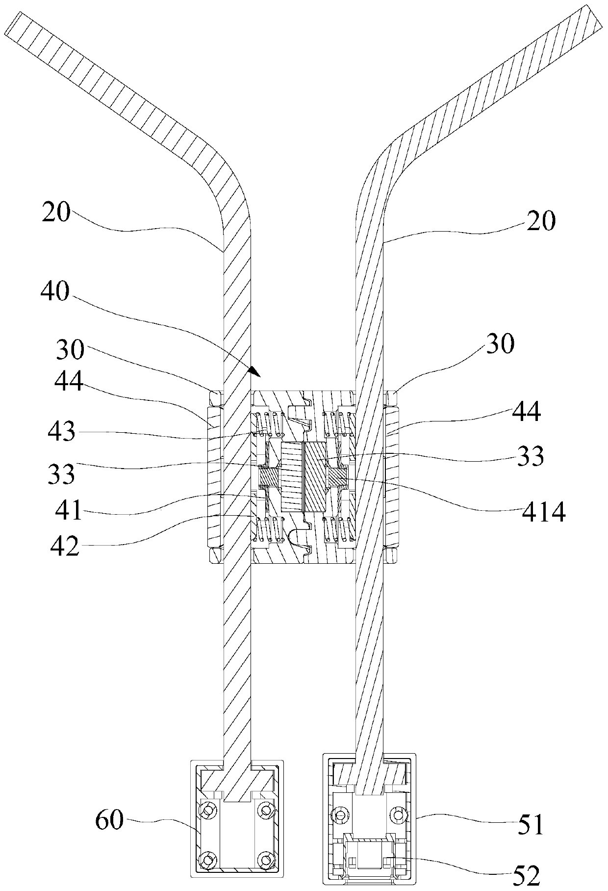
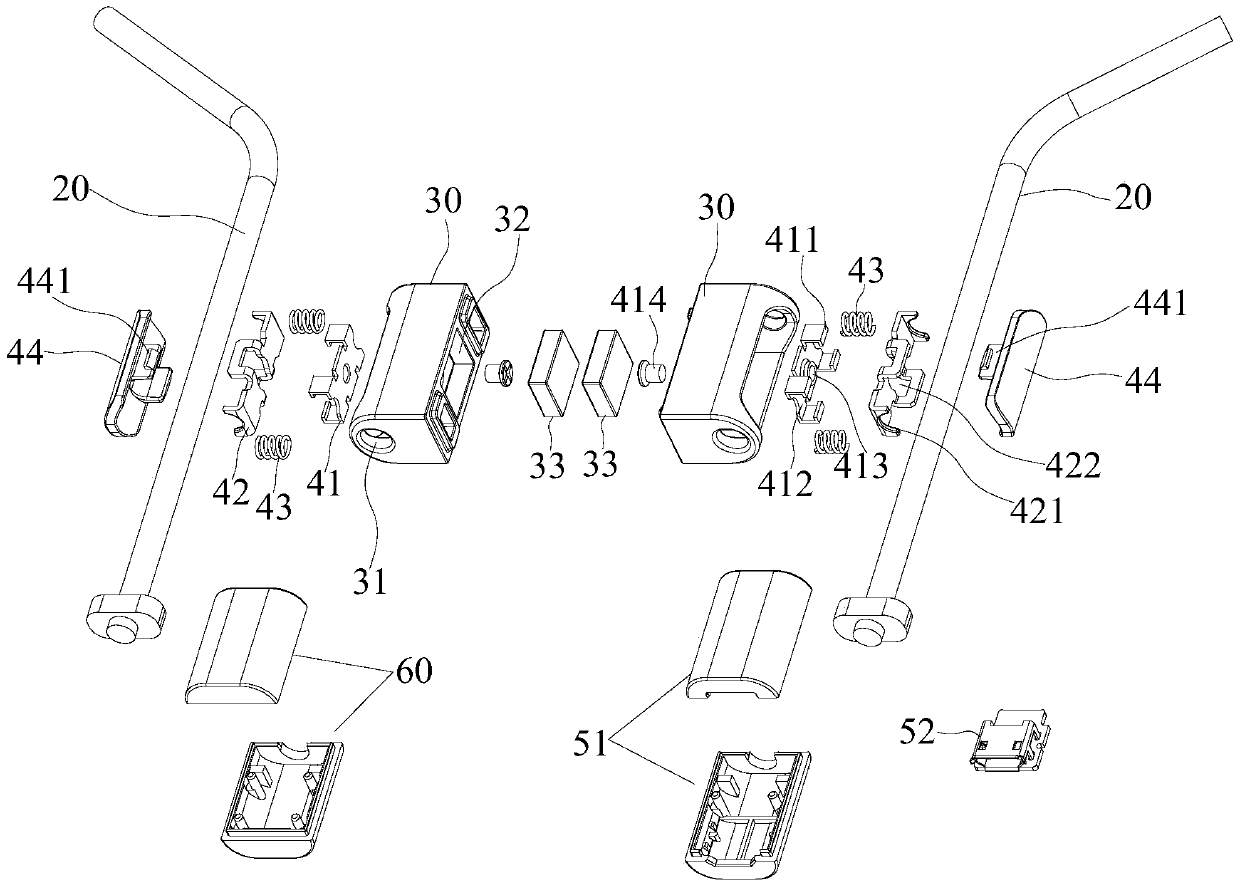
[0039] refer to Figure 1 to Figure 3 In the present embodiment, the neck massager includes a U-shaped neck pillow 10 and drawstrings 20 respectively arranged at both ends of the U-shaped neck pillow 10, and also includes two magnetic boxes 30, each magnetic box 30 is provided with a perforation 31 , the two drawstrings 20 are respectively installed in the two perforations 31, and each magnetic box 30 is provided with a locking structure 40 for clamping / releasing each drawstring 20 respectively. When the locking structure 40 clamps each drawstring 20 When tight, the magnetic box 30 is fixed on the two pull cords 20 ; when the locking structure 40 loosens each pull cord 20 , the magnetic box 30 can move on the two pull cords 20 .

[0040] The U-shaped neck pillow is also provided with a massage assembly (not shown) and a control assembly (not shown) that controls the massage assembly. The control assembly includes a rechargeable battery, and a pull cord 20 is a data transmissio...

Embodiment 2

[0052] refer to Figure 4 to Figure 6 , the locking structure 40 provided in this embodiment includes an elastic member 43 , a locking block 45 and a button 46 . The elastic member 43 is horizontally arranged in the magnetic box 30, and the clamping block 45 leans against the outside of the elastic member 43. Two second semicircular holes 451 are provided at the front and rear of the clamping block 45 for the drawstring 20 to pass through, and the button 46 is arranged on the clamping block. 45 and the inner side of the key 46 are provided with two third hooks 461 for pressing the block 45 inwardly, and the two third hooks 461 are hooked on the block 45 .

[0053] In this embodiment, the principle of locking and unlocking of the locking structure 40 is the same as that of the first embodiment, but the specific structure is different. Wherein, the upper end and the lower end of the clamping block 45 protrude two connecting blocks 452 towards the key 46 respectively, and each c...


PUM


Abstract

A neck portion massage apparatus, comprising a U-shaped neck pillow (10) and pull cords (20) respectively provided at two end portions of the U-shaped neck pillow (10). Magnetic boxes (30) are respectively movably provided on the pull cords (20), and the two magnetic boxes (30) can mutually attract. A locking and fastening structure (40) is provided inside the magnetic boxes (30) for engaging and fastening to the pull cords (20). Upon performing a massage, the two magnetic boxes (30) are moved at an upper portion of the pull cords (20) and are fastened thereto utilizing the locking and fastening structure (40); at the same time, the two magnetic boxes (30) are attached together; thus, the two end portions of the U-shaped neck pillow (10) are locked and fastened together by the two magnetic boxes (30), and the U-shaped neck pillow (10) can stably enclose a neck portion for massage, and the U-shaped neck pillow (10) will not fall off even if disturbed during the massage. Compared to an existing neck portion massage apparatus, the use of two magnetic boxes (30) frees both hands, and does not require both hands to secure or pull and fasten the two ends of the U-shaped neck pillow (10), making the overall massage more relaxing and comfortable. When the massage is finished, the two magnetic boxes (30) are separated, and the two end portions of the U-shaped neck pillow (10) are loosened, allowing the U-shaped neck pillow (10) to be conveniently removed from the neck portion.

Description

technical field [0001] The invention relates to the technical field of massagers, and more specifically, relates to a neck massager. Background technique [0002] The current neck massager includes a U-shaped neck pillow and drawstrings located at both ends of the U-shaped neck pillow. When massaging, put the U-shaped neck pillow on the neck, and then pull the drawstring with both hands to fix the U-shaped neck pillow. Avoid the U-shaped neck pillow falling off due to vibration during massage. Adopt this neck massager to carry out massage, although neck has been relaxed, both hands are doing tensioning action all the time, like this, both hands are not only very tired, when massaging neck, both hands are also inconvenient to do other things. Contents of the invention [0003] The object of the present invention is to provide a neck massager, aiming to solve the problem of inconvenient massage caused by the need for both hands to assist the neck massager in the prior art. ...

Claims


Application Information

Patent Timeline
Patent Type & Authority Patents(China)
IPC IPC(8): A61H23/02
CPCA61H23/02
Inventor 马学军吴镜雄
Owner SHENZHEN BREO TECH CO LTD
Learn More