Hollow capsule manufacturing device

A technology for preparing a device and a hollow capsule, which is applied in the directions of capsule delivery, pharmaceutical formulation, and drug delivery, etc., can solve the problems of high cost of cleaning the glue tank and debugging of the glue solution, stuck rails, small strips of strips, and reversed strips. , to save the cost of manpower and material resources, prevent collision or jamming, and eliminate the effect of stripping and reversing strips.

Active Publication Date: 2015-11-11
ANHUI HUANGSHAN CAPSULE CO LTD
View PDF7 Cites 1 Cited by
  • Summary
  • Abstract
  • Description
  • Claims
  • Application Information

AI Technical Summary

Problems solved by technology

[0003] 1. During the splicing process of the large dial template of the glue dipping machine, after long-term use of the small dial retaining strips at both ends of the template, the fatigue degree increases and is easy to deform. During the splicing process, there are strips and inverted strips;
[0004] 2. During the dipping process of the large-scale template dipping, when the glue dipping machine fails and stops, the mold strips are easy to fall into the glue tank, which not only causes pollution, but also consumes a lot of glue tank cleaning and glue adjustment in the later stage, and the cost is very high ;
[0005] 3. During the process of removing static electricity from the hollow capsule, the formwork is placed on the formwork, and with the transmission of the formwork, it passes through the destaticizing roller brush above the track in turn. Because the formwork itself is heavy, after the formwork is pressed on the formwork, the formwork will be affected. The weight of the pressure causes the center to sink, resulting in the formwo

Method used


Image

  • Hollow capsule manufacturing device
  • Hollow capsule manufacturing device
  • Hollow capsule manufacturing device

Examples


Embodiment Construction

[0034] The present invention will be described in detail below in conjunction with the accompanying drawings.

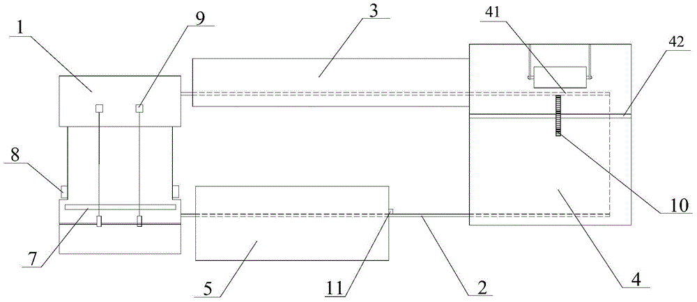
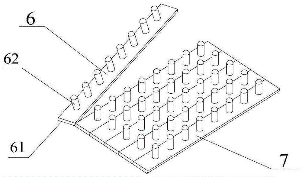
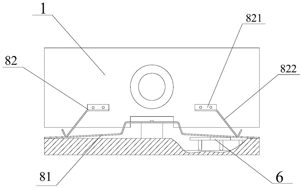
[0035] Such as Figure 1-2As shown, a hollow capsule preparation device includes a glue dipping machine 1, a circulating template delivery track 2, a drying and cooling chamber 3, an electrostatic removal reaction chamber 4, a demoulding device 5, and a small dial 6. The circulating template The transport track 2 connects the glue dipping machine 1, the drying and cooling chamber 3, the static removal reaction chamber 4 and the demoulding device 5 in series to form a circulation system. The small dial 6 includes a base 61 and a Die head 62, the several small dialing strips 6 are assembled into a large dialing template 7 by splicing between bases 61 . The dipping machine 1 includes two large dial templates 7 on each side, a small dial mold retaining device 8, and a template anti-dropping device 9, and the small dial mold retaining device is arranged 8 before and afte...


PUM


Abstract

The invention discloses a hollow capsule manufacturing device. The hollow capsule manufacturing device comprises a glue dipping unit, a circular type mold plate conveying track, a drying and cooling chamber, an electrostatic eliminating reaction chamber, a demolding device and a small mold shifting strip, wherein the glue dipping unit comprises a large mold shifting plate, small mold shifting barrier strip devices and a mold plate anti-dropping device; the small mold shifting barrier strip devices are arranged on a body of the glue dipping unit and positioned at the front end and the rear end of the large mold shifting plate; the mold plate anti-dropping device is arranged on the bottom of the large mold shifting plate; a mold base jacking chain wheel conveying device is arranged in the electrostatic eliminating reaction chamber and is mounted on a supporting beam below a mold base of the electrostatic eliminating reaction chamber; and a mold strip guiding anti-collision device is arranged at the position of an entrance of the circular type mold plate conveying track of the demolding device. The hollow capsule manufacturing device has the advantages that shortcomings of the existing hollow capsule manufacturing device are overcome; the hollow capsule manufacturing device is simple in structure and is stable and reliable; and the running efficiency of the device is improved effectively.

Description

technical field [0001] The invention relates to the technical field of biopharmaceutical equipment, in particular to a hollow capsule preparation device. Background technique [0002] Existing hollow capsule production line devices generally include equipment devices such as a dipping machine, a circulating template conveying track, a drying and cooling room, a static removal reaction chamber, a demoulding device, and a small dial; The process of glue→drying and cooling→static elimination→demolding connects the dipping machine, drying and cooling room, static removal reaction room and demoulding device in series to form an automatic circulation system; however, there are still many problems in the process of operation and use. Mainly focus on the following aspects: [0003] 1. During the splicing process of the large dial template of the glue dipping machine, after long-term use of the small dial retaining strips at both ends of the template, the fatigue degree increases an...

Claims


Application Information

Patent Timeline
IPC IPC(8): A61J3/07
Inventor 叶建国何卫民徐高正
Owner ANHUI HUANGSHAN CAPSULE CO LTD
Why Eureka
Try Eureka