
Space angle adjusting mechanism and space angle adjusting method

A space angle and adjustment mechanism technology, applied in aircraft assembly, aircraft parts, ground installations, etc., can solve problems such as the inability to adjust the space angle, and achieve the effects of improving production efficiency and saving assembly effort

Active Publication Date: 2015-11-11
SHENYANG AIRCRAFT CORP
View PDF5 Cites 6 Cited by
  • Summary
  • Abstract
  • Description
  • Claims
  • Application Information

AI Technical Summary

Problems solved by technology

But only the angle adjustment in one direction can be realized, and the adjustment of the space angle cannot be obtained.

Method used


Image

  • Space angle adjusting mechanism and space angle adjusting method
  • Space angle adjusting mechanism and space angle adjusting method
  • Space angle adjusting mechanism and space angle adjusting method

Examples


Embodiment 1

[0022] A space angle adjustment mechanism

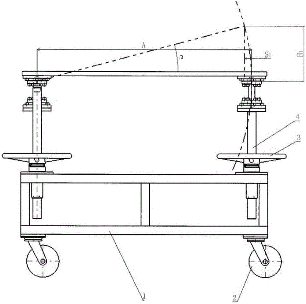
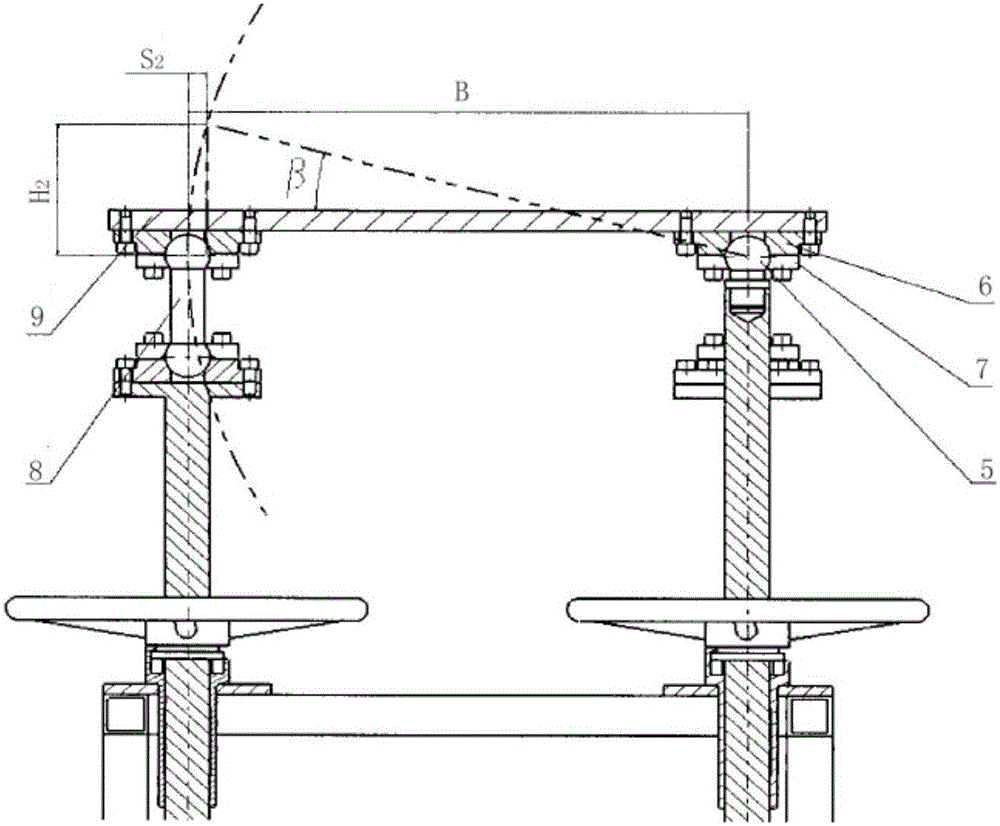
[0023] Such as figure 1 with figure 2 As shown, a space angle adjustment mechanism consists of a car body 1, a universal wheel 2, a hand wheel with a screw nut 3, four lifting screws 4, a single-sided universal ball joint 5, a universal support 6, a press The cover 7 is composed of a double-sided universal ball head 8 and a base plate 9.

[0024] The car body 1 adopts a truss structure, and four universal wheels 2 are screwed on the car body 1 to realize the free movement of the installed car.

[0025] The four lifting screws 4 are respectively matched with the hand wheel 3 with screw nut and installed on the car body 1. On the other end of the three lifting screws 4, a double-sided universal ball head 8 is installed, and the other of the one lifting screw 4 One end is installed with a unilateral universal ball joint 5. The hand wheel 3 with the screw nut and the lifting screw 4 form a spiral transmission to realize the height adjustmen...

Embodiment 2

[0029] Embodiment 2 A method for adjusting the spatial angle

[0030] Using the space angle adjustment mechanism of embodiment 1, the method is as follows: install the parts to be installed or the finished parts between the base plate and the universal support, and drive each lifting screw to move up and down through the handwheel 3 with a screw nut. After determining the mutual distance of the four screws, the center distance A in the length direction and the center distance B in the width direction, make the lifting distance and the corner of the lifting screw meet the following relationship:

[0031] tgα=H 1 / A;

[0032] S 1 = A 2 + H 1 2 - A ;

[0033] Among them, S 1 Compensate the distance for the length direction;

[0034] α is the adjustment angle in the length direction;

[0035] H 1 Adjust the relative height for the lengthwise lifting screw;

[0036] tgβ=H 2 / B;

[0037] S 2 = B 2 + H 2 2 - B ;

[0038] ...


PUM


Abstract

The invention relates to a space angle adjusting mechanism and a space angle adjusting method. The technical scheme is that a space angle adjusting mechanism comprises a vehicle body, hand wheels having nuts, four elevating lead screws, single-sided universal ball heads, double-sided universal ball heads and a foundation plate, wherein the four elevating lead screws are respectively cooperated with the hand wheel having the nuts and then installed on the vehicle body; the other ends of three elevating lead screws are provided with the double-sided universal ball heads; the other end of the elevating lead screw is provided with the single-sided universal ball head; and then the foundation plate is installed. The ball head ends of the single-sided universal ball heads or the double-sided universal ball heads are connected with a universal bearer and fixed by a gland; and the universal bearer is movably connected with the foundation plate. Three double-sided universal ball heads are cooperated with one single-sided universal ball head structure to achieve spatial angle required for intersection point docking via distance and angle compensation between the lead screws; less efforts are required for assembling of parts or finished products on an air plane; and production efficiency can be improved.

Description

Technical field [0001] The invention belongs to the field of ground equipment, and in particular relates to a mechanism and method for realizing the fine adjustment of the spatial angle when installing aircraft parts or finished parts so as to make the connection of intersection holes more rapid and labor-saving. Background technique [0002] In the aircraft department and the general assembly process, there is a problem of assembling parts or finished parts on the aircraft. The connection method is generally the butt joint of the intersection hole, and the full pin, so the adjustment of the spatial angle is required during installation. The conventional ground equipment installation vehicle realizes the angle change by using two screw rods or four screw rods to make a round hole on one side and a long round hole on the other side. However, only one direction of angle adjustment can be achieved, and no spatial angle adjustment can be achieved. Summary of the invention [0003] I...

Claims


Application Information

Patent Timeline
Patent Type & Authority Applications(China)
IPC IPC(8): B64F5/00B64F5/10
Inventor 曹烈王子军
Owner SHENYANG AIRCRAFT CORP
Learn More