
Stop valve

A shut-off valve and valve stem technology, which is applied in the field of valve manufacturing, can solve the problems of easy damage of the valve stem, long closing time, and shut-off valve opening, so as to avoid strain or damage, quickly separate, and improve the service life.

Inactive Publication Date: 2015-11-11
NEWAY VALVE SUZHOU
View PDF5 Cites 0 Cited by
  • Summary
  • Abstract
  • Description
  • Claims
  • Application Information

AI Technical Summary

Problems solved by technology

[0005] Therefore, the technical problem to be solved by the present invention lies in the defects in the prior art that the cut-off valve takes a long time to open and close and the valve stem is easily damaged, so as to provide a cut-off valve with short opening and close time and the valve stem is not easily damaged.

Method used


Image

  • Stop valve
  • Stop valve
  • Stop valve

Examples


Embodiment Construction

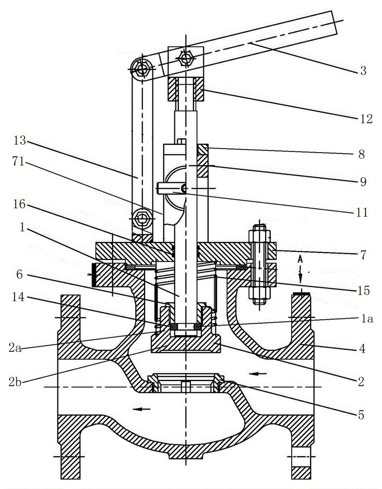
[0037] Such as figure 2 As shown, this embodiment provides a shut-off valve, including a valve body 4 with a top opening, a valve cover 7 sealingly connected to the top opening, and a valve stem extending into the inside of the valve body 4 through the valve cover 7 for sealing. 1. The valve disc 2 connected to the bottom of the valve stem 1 and located inside the valve body 4, and the valve seat 5 with an opening arranged inside the valve body 4, the valve stem 1 can go up and down under the action of the control mechanism The movement drives the valve disc 2 to open or close the opening on the valve seat 5, the control mechanism includes a support rod 13 arranged on the valve cover 7, an operating rod 3 movably connected to the support rod 13, the The operating rod 3 is movably connected with the top of the valve rod 1, and the operating rod 3 can swing under the action of an external force to drive the valve rod 1 to move up and down, and also includes a driving mechanism ...


PUM


Abstract

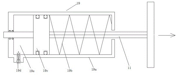
The invention discloses a stop valve which comprises a valve body, a valve deck, a valve rod, a valve clack, a valve base and a control mechanism. The valve deck is connected to the top of the valve body in a sealed manner. The valve rod penetrates the valve deck in a sealed manner to stretch into the valve body. The valve clack is connected to the bottom of the valve rod and located in the valve body. The valve base is arranged in the valve body. The valve rod moves up and down under the action of the control mechanism so as to drive the valve clack and the valve base to be opened or closed. The control mechanism comprises a supporting rod, an operating rod and a driving mechanism with a pin shaft. The supporting rod is arranged on the valve deck, and the operating rod is movably connected to the supporting rod. The operating rod is movably connected with the top of the valve rod. The operating rod can swing under the external force action so as to drive the valve rod to move up and down. The pin shaft of the driving mechanism can be arranged on the movement path of the valve rod in a telescopic manner and is used for limiting the valve rod at the needed height. The valve can be rapidly opened only by exerting external force on the operating rod to enable the operating rod to swing and directly drive the valve rod to ascend. A compression spring is arranged between the valve clack and the valve deck. Under the effect of the compression spring, the valve can be rapidly closed.

Description

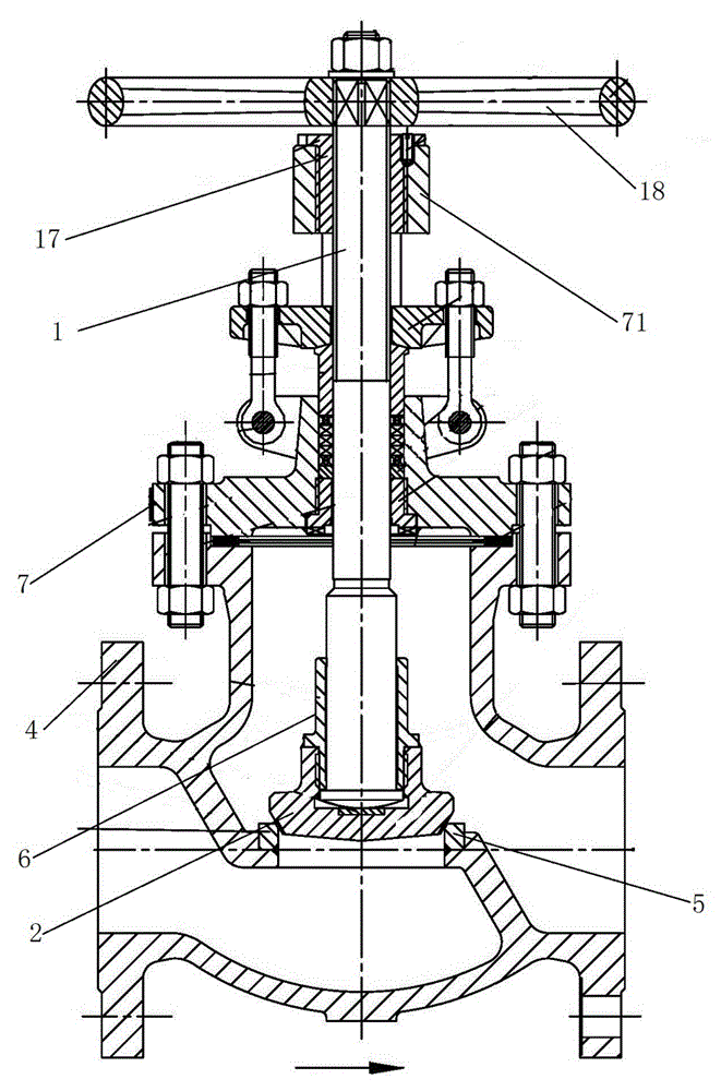
technical field [0001] The invention relates to a shut-off valve, which belongs to the technical field of valve manufacture. Background technique [0002] The valve plays the role of cutting off and throttling the medium in the pipeline where it is located. As an extremely important cut-off valve, the globe valve applies torque to the valve stem, and the valve stem exerts torque on the valve disc in the axial direction. The pressure makes the valve disc and the valve seat fit closely to form a sealing surface, preventing the medium from leaking along the sealing surface. [0003] The structure of the traditional globe valve is as follows: figure 1 As shown, including the valve stem 1, a valve disc 2 is fixed on one end of the valve stem 1, and a sealing surface is formed between the valve disc 2 and the valve seat 5 located in the valve body 4, and the other end of the valve stem 1 is provided with a hand wheel 18, A valve stem nut 17 is threadedly connected to the valve s...

Claims


Application Information

Patent Timeline
Patent Type & Authority Applications(China)
IPC IPC(8): F16K1/00F16K31/14
CPCF16K1/00F16K31/14
Inventor 陈庆刚
Owner NEWAY VALVE SUZHOU
Learn More