Bucket brace and method for use

a technology of buckets and braces, which is applied in the direction of container/bottle construction, rigid containers, lighting support devices, etc., can solve the problems of buckets being prone to spin, causing injury to the second worker or even the first worker, and either technique is somewhat dangerous, so as to avoid physical strain and manufacture cheaply

Inactive Publication Date: 2007-08-28
DPS
View PDF16 Cites 21 Cited by
  • Summary
  • Abstract
  • Description
  • Claims
  • Application Information

AI Technical Summary

Benefits of technology

[0023]An advantage of the present invention is to prevent a bucket from spinning while its contents are being mixed together.
[0024]Another advantage of the present invention is to help workers avoid physical strain and the dangers associated with standing on top of a bucket.
[0025]An additional advantage of the present invention is to function simply, by applying foot pressure to a bucket dropped into the brace, and safely, without any danger of the bucket tipping in the direction in which foot pressure is being applied.
[0026]A final advantage of the present invention is that it can be manufactured inexpensively.

Problems solved by technology

When the mixer is activated in the materials in the bucket, the bucket tends to spin.
Either technique is somewhat dangerous, as mixing in this manner may result in injury to the second worker or even to the first worker, due to strain on the worker's lower back and other muscles while attempting to maintain the awkward position required to both control the mixer and steady the bucket.
In addition, if the worker holding the bucket is distracted or in any way relaxes his control of the bucket, then the bucket can spin rapidly and injure either the second worker, if there is one, or the single worker's lower legs by the concussion of the bucket onto the worker's hands or legs, respectively.
While this generally keeps the bucket steady, this position is potentially dangerous in that the bucket could break or the worker could slip.
Moreover, dirt from the bottom of the worker's boots can easily fall into the bucket contents from this position.
If the bucket is not steadied in some manner prior to engaging the mixer with the contents of the bucket, the bucket will rotate in the same direction as the direction of mixing, and then will rapidly spin in an uncontrolled fashion.
Spillage of the contents of the bucket will result.
Other inventions have addressed this problem, but they are all either inherently prone to tipping the bucket, bulky, or otherwise inconvenient.
This device inherently applies pressure on one side of the bucket only, thus leaving the bucket unbalanced and vulnerable while additional forces are exerted on the bucket through the mixing of the bucket contents.
In addition, this tool has a sharp edge and is limited to use on buckets that have handles.
Moreover, its usefulness in buckets that are only partially filled is questionable, as even less stability is afforded when the weight of the bucket contents is significantly less than when a bucket is full.
This device provides no support to the bucket other than at the base, and the design is inherently subject to the danger of tipping.
However, this notched design requires use of pails with mating notches, which are not commonly available.
This device is bulky, limits the ability of the worker to move the mixer while stirring the contents of a bucket, and requires the worker to use both feet to secure the bucket.
This device is formed of plastic materials to facilitate the intended distortion that provides frictional restraint against rotation of the pail, and thus is subject to breakage under the tremendous strain that the design and materials will experience during use.

Method used


Image

  • Bucket brace and method for use
  • Bucket brace and method for use
  • Bucket brace and method for use

Examples


Embodiment Construction

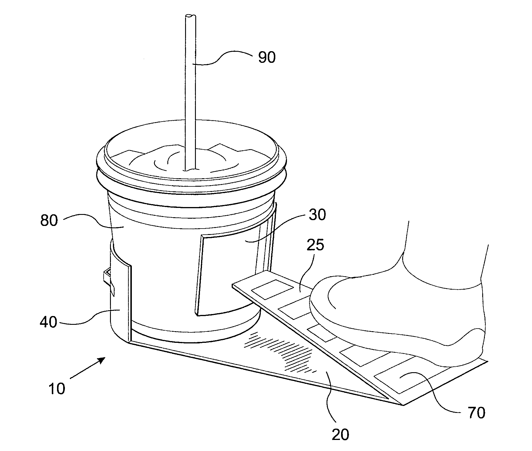
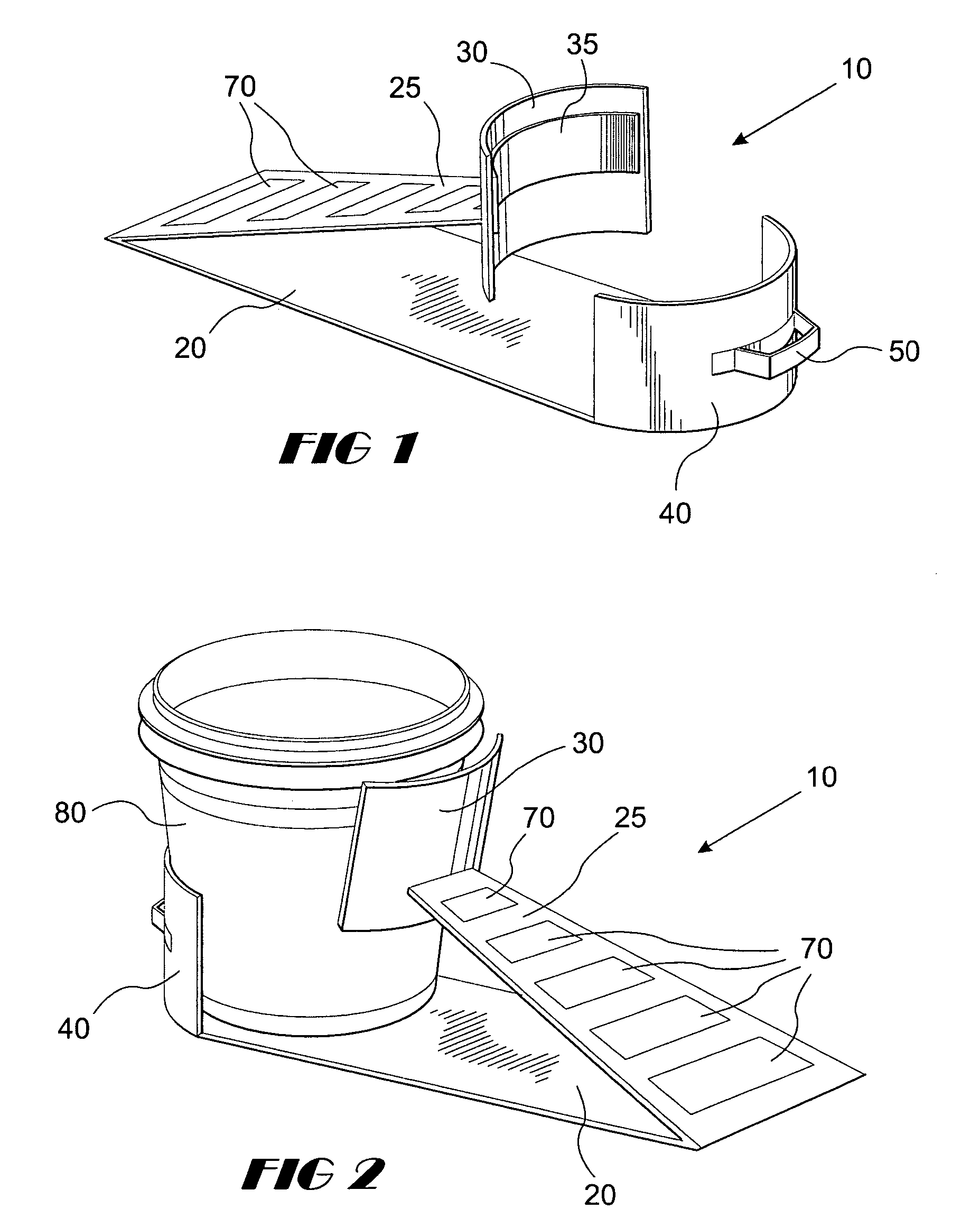
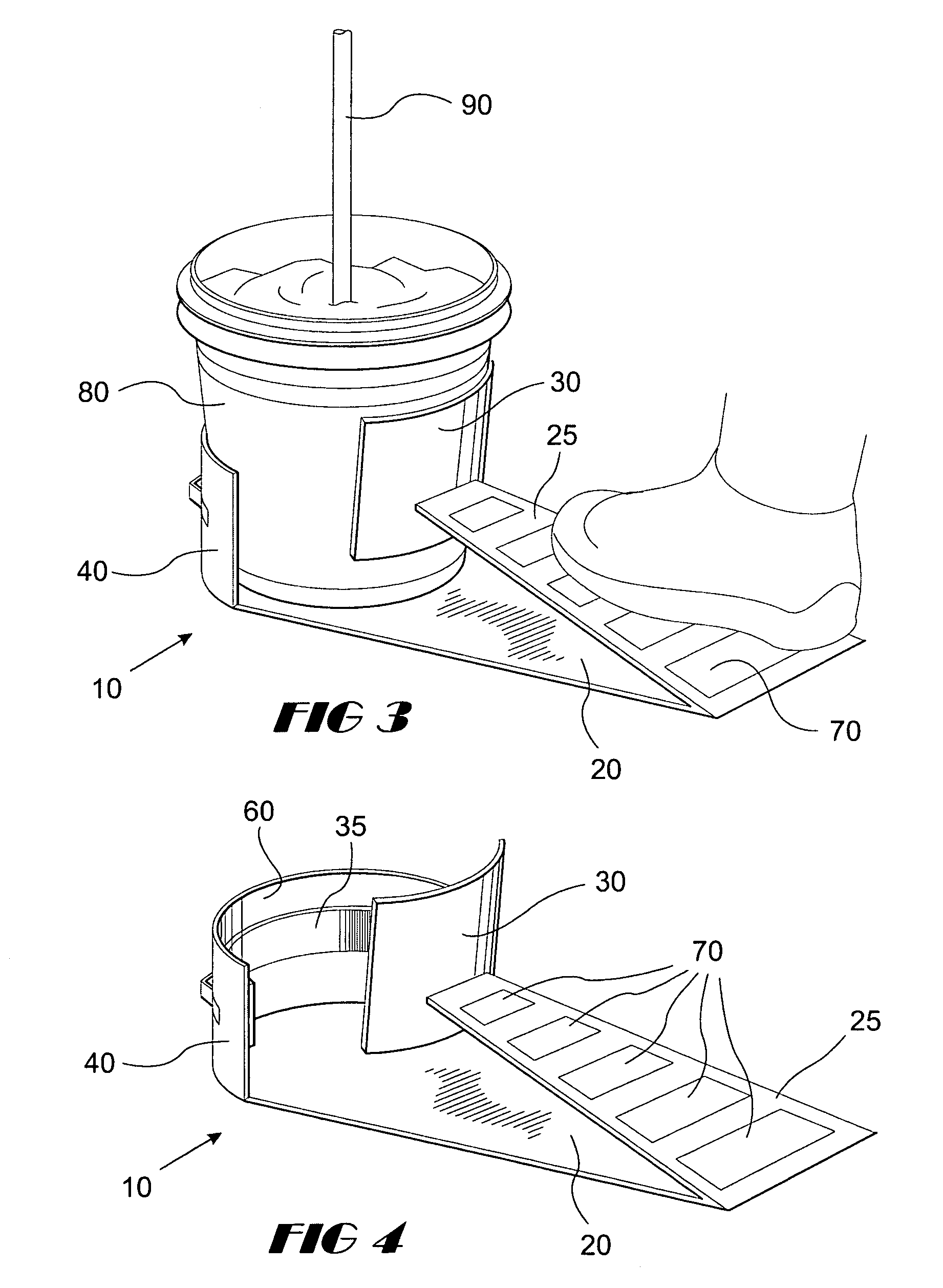
[0033]Referring in detail to the drawings and with particular reference to FIGS. 1 and 2, a bucket brace 10 for holding down a bucket 80 securely to prevent rotation while a mechanical mixer is used to mix a viscous fluid in the bucket is illustrated. A bucket brace 10 has a base 20 and foot pressure portion 25, which preferably are fabricated from an elongated piece of rigid material such as steel or other metal, polyvinylchloride (PVC) or other plastic, fiberglass, or silicone, or of semi-rigid material such as rubber, that is folded. Alternatively, a hinge or hinges or other device could be used to achieve the relative placement of the base and foot pressure portion. The foot pressure portion 25 has front support 30 attached, preferably perpendicularly, to its unfolded or unhinged end. Both foot pressure portion 25 and front support 30 may be provided with a high friction patterned material 35 to provide extra traction. The unfolded end of base 20 is fitted with rear support 40. ...


PUM


Abstract

A bucket brace holds a bucket in place while the bucket's contents are mixed or stirred. The bucket brace prevents the bucket from spinning due to the mixing. The bucket brace is an assembly made up of four parts: a base, a foot pressure portion, a front support, and a rear support. A handle is provided for carrying the base. The front and rear supports are of semi-circular shape, and are made of rigid or semi-rigid material, as are the base and the foot pressure portion. The foot pressure portion and the base are integral, preferably both parts being formed from the same piece of material. The foot pressure portion and the rear support preferably have surface grip portions. The handle may be made of any suitable material, preferably the same rigid or semi-rigid material as the other parts of the bucket brace. A method of use for employing the brace to hold a bucket in place while stirring or mixing the contents of the bucket is also described whereby the user places a bucket in the brace and applies foot pressure to the foot pressure portion to prevent the bucket from spinning while the user stirs or mixes the bucket contents.

Description

BACKGROUND OF THE INVENTION[0001]1. Field of the Invention[0002]This invention relates generally to construction tools and in particular to a bucket brace tool and method for use of the same that enables a user to apply foot pressure against the bucket brace to prevent rotation of the bucket during stirring or mixing of the bucket's contents.[0003]2. Description of the Background Art[0004]The construction industry utilizes gypsum drywall taping compounds and pails of premixed plaster. Some drywall compounds must be mixed with water prior to application. Premixed plaster is supplied in 25 kg buckets in which cement must be mixed with the plaster before being applied as a patching and finishing compound. In both cases, a portable mixer having mixing paddles that rotate at approximately 400 to 600 rpm is used to mix the viscous or cementitious materials. When the mixer is activated in the materials in the bucket, the bucket tends to spin. To prevent the bucket from rotating, the constr...

Claims


Application Information

Patent Timeline
Patent Type & Authority Patents(United States)
IPC IPC(8): A47G23/02
CPCB01F15/00733B01F2215/0047B01F35/42B01F2101/28
Inventor DUNSON, JESSIE L.
Owner DPS
Why Eureka
Try Eureka