Wireless humidifier

A humidifier, wireless technology, applied in the direction of air humidification system, heating method, lighting and heating equipment, etc., can solve the problems of bulky, inconvenient to carry, uneven humidification, etc., to achieve a wide range of applications, easy to carry, healthy and comfortable environment Effect

Inactive Publication Date: 2015-11-11
广西鹿寨县华顺茧丝有限责任公司
View PDF5 Cites 2 Cited by
  • Summary
  • Abstract
  • Description
  • Claims
  • Application Information

AI Technical Summary

Problems solved by technology

[0003] However, the ultrasonic humidifiers on the market are generally large in size and placed in the place where the power plug is placed. It is inconvenient to carry and cannot be used in places without a power plug. Therefore, people usually place it in a fixed place in the room for use. If things go on like this, the degree of local humidification in the room is much greater than other places, and the humidification is uneven

Method used


Image

  • Wireless humidifier

Examples


Embodiment 1

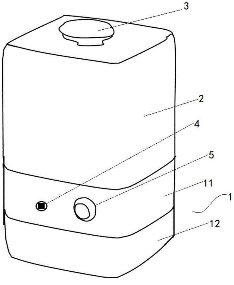
[0020] Example 1: figure 1 The structural diagram of the wireless humidifier provided by the embodiment of the present invention, it can be clearly seen from the figure that the wireless humidifier provided by this embodiment includes a base 1, a water tank 2, and a nozzle 3, and the upper end surface of the base 1 A fogging chamber 11 is formed by being concave, and the base body 1 is also provided with a power supply part 12, the power supply part 12 includes a power supply, and an atomizing sheet is arranged in the fogging chamber 11, and the power supply is the atomizing sheet For power supply, the water tank 2 is arranged on the base body 1, and the water tank is provided with a drainage channel and a mist removal channel communicating with the fogging chamber 11, and the water stored in the water tank 2 is discharged into the air through the drainage channel. The mist generating chamber 11 and the nozzle 3 are in communication with the outlet of the mist discharge passag...

Embodiment 2

[0028] Example 2: figure 1 The structural diagram of the wireless humidifier provided by the embodiment of the present invention, it can be clearly seen from the figure that the wireless humidifier provided by this embodiment includes a base 1, a water tank 2, and a nozzle 3, and the upper end surface of the base 1 A fogging chamber 11 is formed by being concave, and the base body 1 is also provided with a power supply part 12, the power supply part 12 includes a power supply, and an atomizing sheet is arranged in the fogging chamber 11, and the power supply is the atomizing sheet For power supply, the water tank 2 is arranged on the base body 1, and the water tank is provided with a drainage channel and a mist removal channel communicating with the fogging chamber 11, and the water stored in the water tank 2 is discharged into the air through the drainage channel. The mist generating chamber 11 and the nozzle 3 are in communication with the outlet of the mist discharge passag...


PUM


Abstract

The invention relates to the field of small household appliances, and discloses a wireless humidifier. The wireless humidifier comprises a seat body, a water tank and a nozzle, wherein the upper end face of the seat body is downwards concave to form a fogging cavity; a power source part is also arranged on the seat body; the power source part comprises a power source; a fogging sheet is arranged in the fogging cavity; the power source is used for supplying power for the fogging sheet; the water tank is arranged on the seat body; the water tank is provided with a drainage channel and a fog discharge channel which are communicated with the fogging cavity; water stored by the water tank is drained into the fogging cavity by the drainage channel; the nozzle is communicated with an outlet of the fog discharge channel; and water fog produced by the fogging of the fogging sheet is discharged by the fog discharge channel and the nozzle in sequence. The wireless humidifier has the advantages that the wireless humidifier is convenient to carry and can be used in real time; the application occasions are wide; uniform humidification is realized; and a healthy and comfortable environment is created.

Description

technical field [0001] The invention relates to the field of small household appliances, in particular to a wireless humidifier. Background technique [0002] A humidifier is a household appliance that increases room humidity. Ultrasonic technology is a relatively mature technology that has been widely used in various fields. The ultrasonic humidifier adopts 2 million times of ultrasonic high-frequency vibration per second to atomize water into 1-5 micron ultrafine particles and negative oxygen ions to achieve uniform humidification, freshen the air, improve health, and change the hot and dry winter heating. Create a comfortable living environment. Ultrasonic humidifier is the first choice product recommended for children. It has a high safety factor, purifies the air, has strong sterilization and humidification ability, and improves health. [0003] However, the ultrasonic humidifiers on the market are generally large in size and placed in the place where the power plug i...

Claims


Application Information

Patent Timeline
Patent Type & Authority Applications(China)
IPC IPC(8): F24F6/12
CPCF24F6/12
Inventor 覃光能黄邦强
Owner 广西鹿寨县华顺茧丝有限责任公司
Why Eureka
Try Eureka