
An image capture device for quality inspection and analysis of machine tool guide rail surface

An image capturing and rail surface technology, which is applied to measuring devices, optical devices, instruments, etc., can solve problems such as large detection errors, and achieve the effects of time-consuming and labor-intensive, simple structure and low production cost.

Inactive Publication Date: 2017-10-27
XIANGTAN UNIV
View PDF1 Cites 0 Cited by
  • Summary
  • Abstract
  • Description
  • Claims
  • Application Information

AI Technical Summary

Problems solved by technology

When this device is used, there is still a large detection error, and the application range is limited to the guide rail of the large cylindrical grinding machine bed. Therefore, based on the important influence of the accuracy of the guide rail of the machine tool on the processing quality of the part, it is necessary to use an efficient and simple method Machine tool guideway accuracy detection

Method used


Image

  • An image capture device for quality inspection and analysis of machine tool guide rail surface
  • An image capture device for quality inspection and analysis of machine tool guide rail surface
  • An image capture device for quality inspection and analysis of machine tool guide rail surface

Examples


Embodiment 1

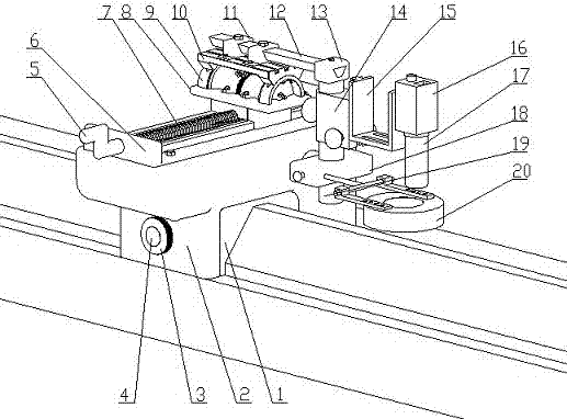
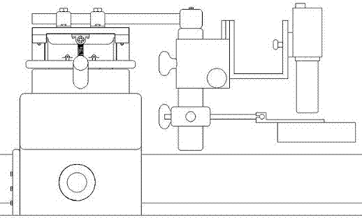
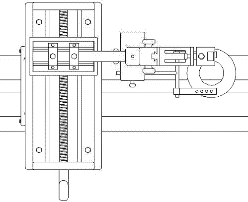
[0025] Embodiment 1, the present invention includes a moving box, a sliding assembly, a rotating assembly, and a shooting assembly; Fitted with the guide rail to be detected; the sliding assembly includes a handle 5, a sliding body 6, a lead screw 7, and a mobile platform 8, the sliding body 6 is fixed above the outer box 2, and the upper surface of the sliding body is provided with Sliding track, the mobile platform 8 is installed above the sliding track, and the lower end is provided with a threaded hole, and one end of the screw 7 is provided with a handle 5, which passes through the threaded hole at the lower end of the mobile platform 8 and is installed on the sliding body 6; The assembly includes a rotating base 9, a worm 21, a rotating platform 10, and a fixed block 11. The rotating base 9 is fixed above the mobile platform 8. The overall shape is semicircular and the diameter at both ends is large and the diameter in the middle is small. There are circumferential guides...

Embodiment 2

[0026] Embodiment 2, the working process of the present invention: connect the light 27 and the eyepiece 17 to an external power supply and a computer, adjust the eyepiece moving device 14, move the square block 18 to an appropriate position and tighten it, and move the light device 20 along the moving square block 18 The inner hole is moved so that the centerline of the eyepiece 17 and the centerline of the light 27 are roughly in a straight line, the relative position of the eyepiece 17 and the light 27 is adjusted by the fine-tuning knob 28 to make the picture quality optimal, and the mobile platform 8 is moved by shaking the handle 5 To the appropriate position, the rotating worm 21 realizes the rotation of the rotating platform 10, so that the eyepiece 17 reaches the position perpendicular to the slope of the guide rail surface, adjusts the fine-tuning knob 28 again to make the shooting effect reach the best, and then shoots, and rotates the handwheel 3 to realize the whole...

Embodiment 3

[0027] Embodiment 3, the inner rail cover 1 in the mobile box described in the present invention moves based on the rail surface to be tested itself. refer to Figure 1 to Figure 6 , all the other are with embodiment 1.


PUM


Abstract

An image capture device used for quality detection and analysis of machine tool guide rail surface. It mainly includes a moving box, a sliding component, a rotating component and a shooting component. The mobile box is mainly composed of an inner guide rail cover 1, an outer box 2, a hand wheel 3, and a built-in friction wheel 4. The sliding assembly is mainly composed of a handle 5, a sliding body 6, a screw 7, and a mobile table 8 The rotating assembly is mainly composed of a rotating base 9, a worm 21, a rotating platform 10, and a fixed block 11. The shooting assembly is connected with the fixed block 11 through a V-shaped rod 12, and mainly includes a sliding rod 19, an eyepiece moving device 14 , U-shaped bracket 15, connector 16, eyepiece 17, moving square block 18, and lighting device 20. It has a simple structure and low manufacturing cost. By replacing the inner guide rail sleeve, images of the guide rail surface of large-scale machine tools with different sections can be quickly and accurately obtained, providing image support for the identification of the wear state of the guide rail surface based on machine vision inspection technology, and finally being able to take effective measures. Mitigate wear or repair rails to provide decision basis. It is of great significance to the maintenance of machine tool precision and product quality assurance, and can be widely used in the field of quality inspection of machine tool guide rail surfaces.

Description

technical field [0001] The invention relates to the field of quality detection of machine tool guide rails, in particular to an image capturing device for detecting and analyzing the quality of machine tool guide rails. Background technique [0002] The accuracy of the guide rail of the machine bed directly affects the size, shape and position error of the machined parts. Therefore, whether it can maintain high-precision machining status will affect the product qualification rate and the service life of the machine tool. Therefore, the accuracy of the guide rail of the machine tool Testing is critical. Since the guide rails of the bed are exposed to the air all the year round without protection, the dustproof and chipproof conditions are poor, and wear will inevitably occur after long-term use. When the wear is serious, the machining accuracy of the parts will not meet the requirements, and even cause The guide rail fails, so wear is the root cause of the decline in the acc...

Claims


Application Information

Patent Timeline
Patent Type & Authority Patents(China)
IPC IPC(8): G01B11/24
Inventor 周友行石弦韦邹凤罗昕尹伟杰杨文佳
Owner XIANGTAN UNIV
Learn More