Centrifugal type wind-blowing-off and pressing-ring tearing-off method of fresh corn husk

A fresh corn, centrifugal technology, applied in threshing equipment, applications, agricultural machinery and tools, etc., can solve the problems of easy scratches on the surface of corn, low corn peeling efficiency, unsatisfactory peeling rate and seed breaking rate, etc. Achieve the effect of thorough peeling and low efficiency

Inactive Publication Date: 2015-11-18
HARBIN YONGYU POWER STATION EQUIP
View PDF6 Cites 1 Cited by
  • Summary
  • Abstract
  • Description
  • Claims
  • Application Information

AI Technical Summary

Problems solved by technology

[0003] The present invention solves the problem that the peeling roller of the existing corn peeling machine directly contacts the corn, the surface of the corn is easily scratched, the rate of peeling and seed breaking is not ideal, and secondary peeling is required manually, resulting in low efficiency of corn peeling, and provides A centrifugal fresh corn husk peeling method by wind blowing and pressure ring

Method used


Image

  • Centrifugal type wind-blowing-off and pressing-ring tearing-off method of fresh corn husk
  • Centrifugal type wind-blowing-off and pressing-ring tearing-off method of fresh corn husk
  • Centrifugal type wind-blowing-off and pressing-ring tearing-off method of fresh corn husk

Examples


specific Embodiment approach 1

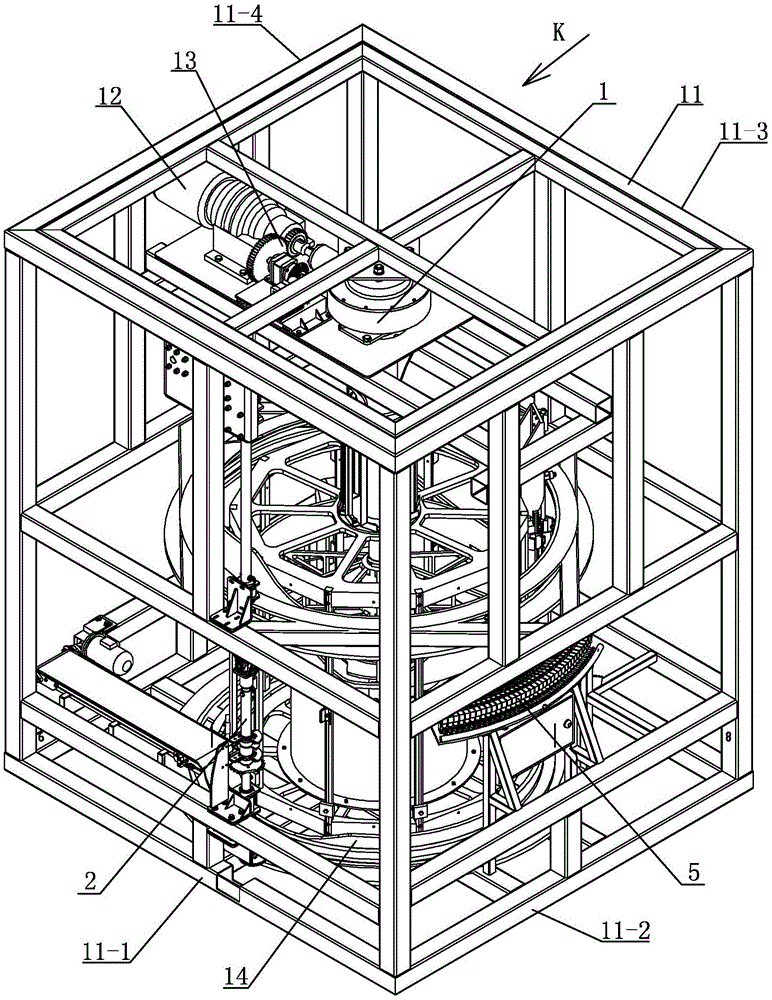
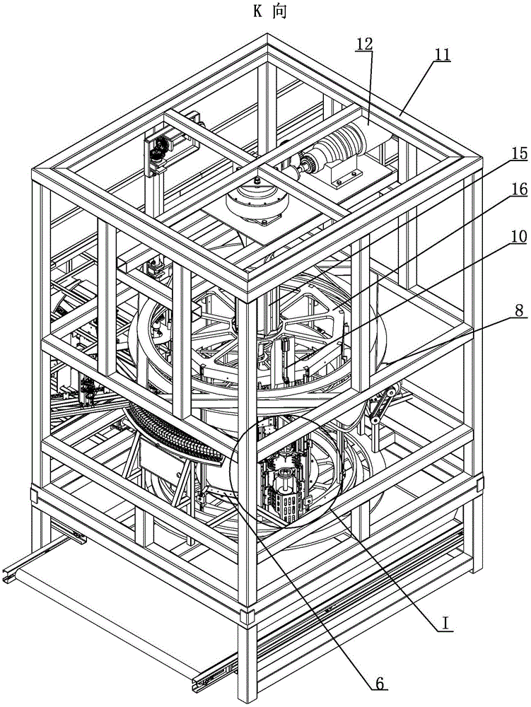
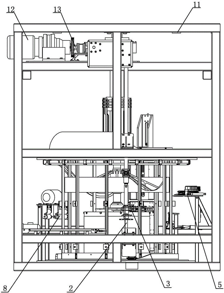
[0028] Specific implementation mode one: combine Figure 1 to Figure 16 Describe this implementation mode, this implementation mode is realized through the following steps:

[0029] Step 1. Install corn: the corn 17 is transported to the rotary knife 2 on the host system 1 by a transport trolley, the corn clamping robot 3 clamps the corn 17 to the rotary knife 2, and the tip of the rotary knife 2 is inserted into the root of the corn , at the same time, the thimble 9-1 on the limit mechanism 9 at the top of the corn is inserted into the top of the corn;

[0030] Step 2. Centrifugally rotate the corn 17: The corn 17 starts to rotate under the drive of the rotary knife 2. The rotating speed of the rotary knife 2 is 200 rpm to 2000 rpm. Due to the centrifugal force, the corn husk 17-1 spreads outwards In an open state, the open state is that the angle α between the corn husk 17-1 and the bottom horizontal plane of the corn 17 is 11°-100°;

[0031] Step 3. Blowing off the corn h...

specific Embodiment approach 2

[0039] Specific implementation mode two: combination figure 1 with image 3 To describe this embodiment, the rotation speed of the rotary knife 2 in the step 2 of this embodiment is 1000 rpm. Other steps are the same as in the first embodiment.

specific Embodiment approach 3

[0040] Specific implementation mode three: combination Figure 12 To illustrate this embodiment, when the corn husk 17-1 is in an open state in Step 2 of this embodiment, the angle α between the corn husk 17-1 and the bottom horizontal plane of the corn 17 is 50°. Other steps are the same as in the first embodiment.


PUM


Abstract

Provided is a centrifugal type wind-blowing-off and pressing-ring tearing-off method of fresh corn husk. The method comprises steps that 1) a corn clamping mechanical arm clamps corn on a spinning knife; 2) driven by the rotary knife, the corn begin to rotate and are scattered outwards in a slightly opened state; 3) when the rotary knife rotates to a blowing mechanism along with a main shaft, the blowing mechanism is started, affected by air pressure, a vertical air nozzle and a side air nozzle blow away the corn husk, and after being blown away, the corn husk are in a horizontally opened state; 4) a stop mechanism stops inertially rotating rotary knife from rotating; and 5) a pressing ring tearing-off part continuous to rotate along with the main shaft. When an upper pressing ring and a lower pressing ring clamp the corn husk and walk to a big wave trough from a small wave trough, the corn husk will be torn off from the corn after being imposed on downwards tearing force by the upper pressing ring and the lower pressing ring. When an upper pressing ring frame and a lower pressing ring frame continuous to enter and go out of the big wave trough, the upper pressing ring is gradually separated from the lower pressing ring, so the corn husk will fall off. Thus, wind-blowing-off and pressing-ring tearing-off for fresh corn husk is finished. The method is used for corn husk stripping.

Description

technical field [0001] The invention relates to a corn peeling method, in particular to a centrifugal fresh corn husk peeling method by wind blowing and pressure ring peeling. Background technique [0002] In the early days, corn peeling was mostly manual peeling. This method was labor-intensive and low in efficiency. In response to this situation, someone invented a corn peeling machine. The corn peeling machine mainly uses two oppositely rotating rollers to make the ear of corn rotate on it. Friction is used to tear and peel off the bracts. Although this method improves the peeling efficiency, due to the high surface hardness of the peeling roller, the corn directly contacts the peeling roller, making the surface of the corn easy to scratch, and the peeling rate and seed breaking rate are not ideal. In practical applications, manual secondary peeling is required, resulting in a reduction in corn peeling efficiency. Contents of the invention [0003] The present inventio...

Claims


Application Information

Patent Timeline
Patent Type & Authority Applications(China)
IPC IPC(8): A01F11/06
Inventor 朱孝胜郑亚军
Owner HARBIN YONGYU POWER STATION EQUIP
Why Eureka
Try Eureka