Seat lifting mechanism

A lifting mechanism and seat technology, applied in the direction of movable seats, etc., can solve the problems of inconvenient lifting operation, unstable seat, unfavorable development and application of locomotives, vehicle driving seats, etc., and achieve good stability and convenient operation Effect

Inactive Publication Date: 2015-11-18
CHENGDU CITY TIANLONG TRANSPORT EQUIP +2
View PDF9 Cites 3 Cited by
  • Summary
  • Abstract
  • Description
  • Claims
  • Application Information

AI Technical Summary

Problems solved by technology

[0002] At present, locomotive and vehicle driving seats adopt a herringbone lifting and shock absorbing mechanism, the lifting stroke is small, the seat is

Method used


Image

  • Seat lifting mechanism
  • Seat lifting mechanism
  • Seat lifting mechanism

Examples


Embodiment 1

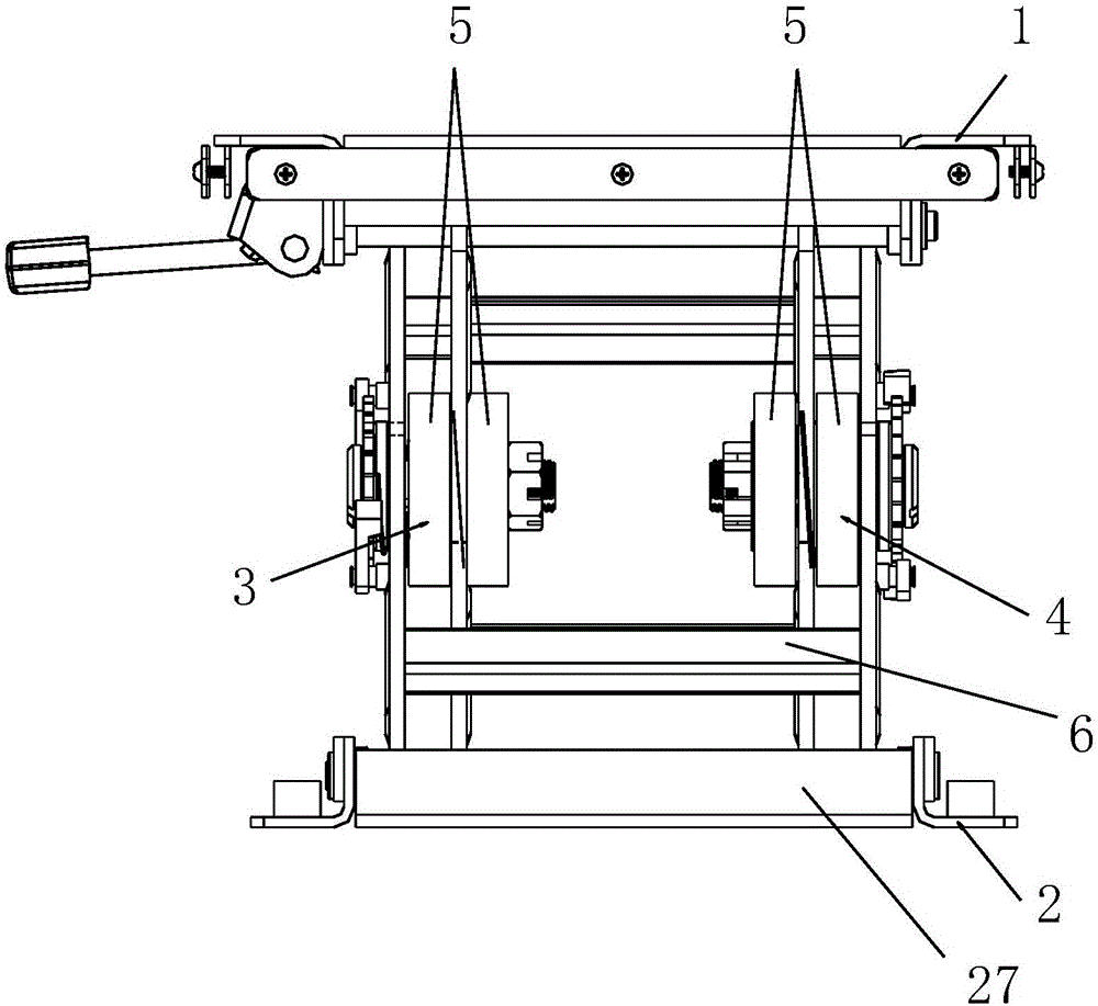
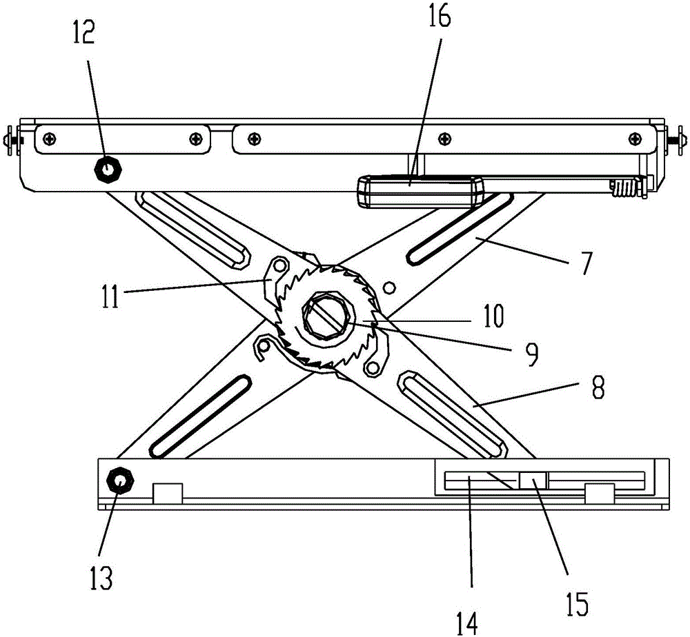
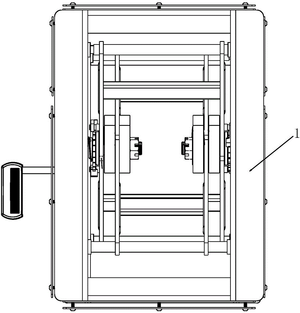
[0044] Such as Figure 1-5 , a seat lifting mechanism, comprising an upper bracket 1, a lower bracket 2, a left scissor frame 3 and a right scissor frame 4 located between the upper and lower brackets. The inner scissors plate 7, the outer scissors plate 8 are respectively provided with in the left and the right scissors frame, and the scroll spring shaft 9 that is contained in the inner and outer scissors plates and can rotate. The ratchet 10 is installed on the scroll spring shaft 9 and is located outside the outer scissor plate 8. The two scroll springs 5 ​​are mounted on the scroll spring shaft 9 and are respectively located on both sides of the inner scissor plate 7 and one end is fixed on the scroll spring shaft 9. And the other end is fixed on the inner scissors board 7. Two upper sliding grooves 25 and two lower sliding grooves 14 are arranged on corresponding positions of the upper and lower brackets. Lower slider 15 is respectively housed in two corresponding chute...

Embodiment 2

[0051] Such as Figures 9 to 13, a seat lifting mechanism, comprising an upper bracket 1, a lower bracket 2, a left scissor frame 3 and a right scissor frame 4 located between the upper and lower brackets. The inner scissors plate 7, the outer scissors plate 8 are respectively provided with in the left and the right scissors frame, and the scroll spring shaft 9 that is contained in the inner and outer scissors plates and can rotate. The ratchet 10 is installed on the scroll spring shaft 9 and is located inside the inner scissor plate 7. The two scroll springs 5 ​​are mounted on the scroll spring shaft 9 and are respectively located on both sides of the inner scissor plate 7 and one end is fixed on the scroll spring shaft 9. And the other end is fixed on the inner scissors board 7. Two upper sliding grooves 25 and two lower sliding grooves 14 are arranged on corresponding positions of the upper and lower brackets. Lower slider 15 is respectively housed in two corresponding ch...


PUM


Abstract

The invention discloses a seat lifting mechanism. The seat lifting mechanism comprises an upper support, a lower support, a left shear rack and a right shear rack. The left shear rack and the right shear rack are each internally provided with an inner shear plate and an outer shear plate. The inner shear plates and the outer shear plates are provided with a rotary volute spiral spring shaft. A ratchet wheel and two volute spiral spring coils are arranged on the volute spiral spring shaft. The two volute spiral spring coils are located on the two sides of the inner shear plates respectively, one end of each volute spiral spring coil is fixed to the volute spiral spring shaft, and the other end of each volute spiral spring coil is fixed to the corresponding inner shear plate. Two upper sliding grooves and two lower sliding grooves are formed in the corresponding positions of the upper support and the lower support. Lower sliders are installed in the two lower sliding grooves respectively. An upper slider is installed in one of the two upper sliding grooves. A locking slider is arranged in the other of the two upper sliding grooves. A lower slider connection rod is connected between the two lower sliders. The upper slider and the locking slider are connected through an upper slider connection rod. A gear groove is formed in the end of the locking slider. The seat lifting mechanism further comprises a stabilizing mechanism. Compared with the prior art, the seat lifting mechanism is convenient and stable to operate.

Description

technical field [0001] The invention relates to a lifting mechanism, in particular to a seat lifting mechanism. Background technique [0002] At present, locomotive and vehicle driving seats adopt a herringbone lifting and shock absorbing mechanism, the lifting stroke is small, the seat is unstable, and the lifting operation is inconvenient, which is very unfavorable for the development and application of locomotive and vehicle driving seats. Contents of the invention [0003] One of the objects of the present invention is to provide a seat lifting mechanism, which is easy to operate and has good stability. [0004] The technical solution is: a seat lifting mechanism, the seat lifting mechanism includes an upper bracket, a lower bracket, a left scissor frame and a right scissor frame, and the left scissor frame and the right scissor frame are located between the upper and lower brackets The left and right scissor frames are respectively provided with an inner scissors pla...

Claims


Application Information

Patent Timeline
IPC IPC(8): B60N2/16
Inventor 张云琨张里波
Owner CHENGDU CITY TIANLONG TRANSPORT EQUIP
Why Eureka
Try Eureka