High-speed train shaft-mounted brake disc with slider structure

A technology for high-speed trains and brake discs, applied in the direction of brake discs, etc., can solve the problems of increasing bolts, brake disc bolt breakage, and reducing the cost of brake discs, so as to reduce costs, reduce the risk of bolt fatigue fracture, and manufacture Safe and reliable dynamic performance

Active Publication Date: 2015-11-18
CRRC QINGDAO SIFANG ROLLING STOCK RES INST
View PDF5 Cites 16 Cited by
  • Summary
  • Abstract
  • Description
  • Claims
  • Application Information

AI Technical Summary

Problems solved by technology

Although this method can ensure that the disc body and the disc hub will not rotate relative to each other when the brake is applied under normal conditions, once the fault condition of superimposed emergency braking and parking braking occurs on the train, the huge braking friction torque will directly Serious relative rotation between the disc body and the disc hub or even shearing of the bolts will result in very serious consequences; in addition, the brake discs of the CRH series EMUs often break bolts, which is because the bolts are in a state of large pre-tightening force for a long time. Increased risk of bolt fatigue fracture
If it is necessary to ensure that the bolts will continue under the action of a large pre-tightening force, the material and processing technology of the bolts must be improved, which is not conducive to reducing the cost of the brake disc.

Method used


Image

  • High-speed train shaft-mounted brake disc with slider structure
  • High-speed train shaft-mounted brake disc with slider structure
  • High-speed train shaft-mounted brake disc with slider structure

Examples


Embodiment 1

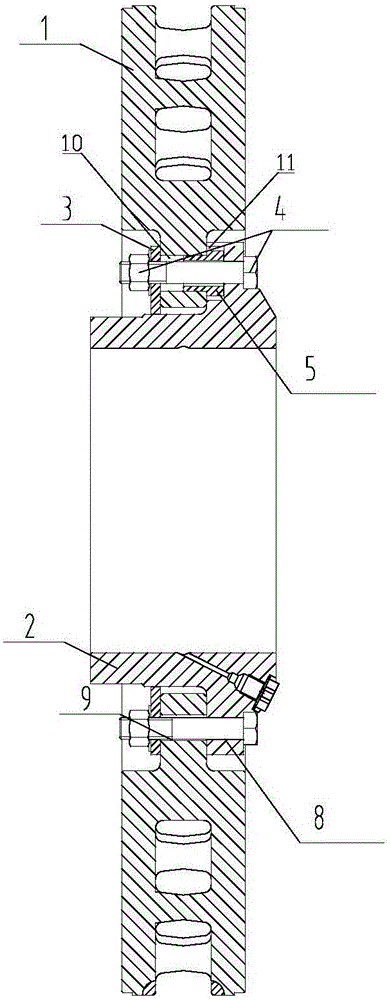
[0019] A high-speed train shaft-mounted brake disc with a slider structure, including a disc body 1, a disc hub 2, a pressure plate 3 and a fastener 4. There are 9 equally circumferentially distributed teeth on each of the disc body 1 and the disc hub 2, and each There are mounting holes on the teeth. The mounting holes include bolt holes and slider holes; multiple slider holes are arranged at intervals with the bolt holes. Such as figure 1 As shown, the bolt holes 8 on the bottom and the bolt holes 9 on the hub are aligned and fixed by fasteners 4; the holes on the top are the slider holes, which are used to install the slider 5.

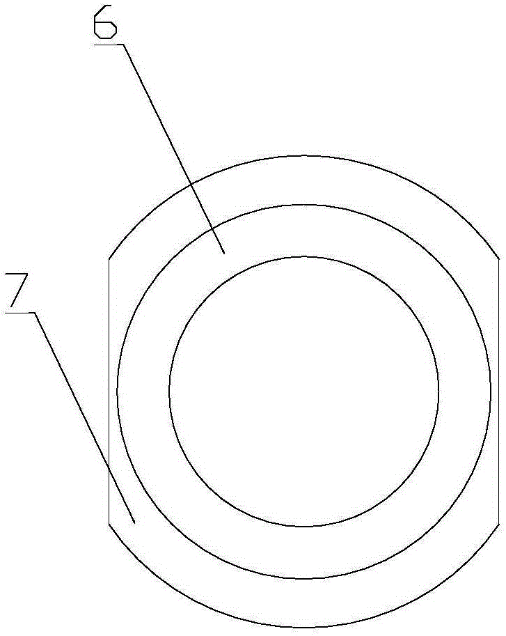
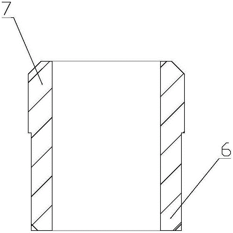
[0020] The slider 5 includes an upper end 6 and a lower end 7, the upper end 6 and the lower end 7 are concentric stepped cylindrical shaft structures, the slider 5 has a through hole passing through the upper end 6 and the lower end 7, and the outer diameter of the upper end 6 is less than The outer diameter of the lower end 7. The size of the ...

Embodiment 2

[0024] The difference from Embodiment 1 is that the lower end 7 of the slider is cylindrical. Correspondingly, the shape of the hub slider hole 11 needs to match the structural change of the lower end portion 7 accordingly, and is a cylindrical hole.


PUM


Abstract

A high-speed train shaft-mounted brake disc with a slider structure comprises a disc body, a disc hub, pressing plates and fasteners. The disc body and the disc hub are each provided with teeth which are evenly distributed in the circumferential direction. Each tooth is provided with an installation hole. The installation holes formed in the disc body and the disc hub are fixed through the fasteners. The high-speed train shaft-mounted brake disc further comprises sliders. Each slider comprises an upper end and a lower end which are of a concentric step cylindrical shaft structure. Each slider is provided with a through hole penetrating through the corresponding upper end and the corresponding lower end. The outer diameter of each upper end is smaller than that of the corresponding lower end. Each installation hole comprises a bolt hole body and a slider hole body. The slider hole bodies are formed at intervals. The upper end of each slider is inserted in the corresponding slider hole body in the disc body. The lower end of each slider is inserted in the corresponding slider hole body in the disc hub. According to the high-speed train shaft-mounted brake disc, the structure of an original brake disc is changed, and the sliders are additionally arranged on the basis of maintaining the disc body, the disc hub, the pressing plates and the fasteners. It can be directly guaranteed that the disc body and the disc hub cannot rotate relatively through the sliders. Meanwhile, the risk of breakage of bolts is lowered indirectly.

Description

technical field [0001] The invention belongs to the technical field of train braking devices, and relates to a brake disc structure, in particular to a high-speed train shaft-mounted brake disc with a slider structure. Background technique [0002] At present, the basic brakes of CRH series EMUs in China all adopt disc brakes, while the trailers of EMUs are all equipped with shaft-mounted brake discs. The current CRH series EMU shaft-mounted brake disc is mainly composed of a disc body, a disc hub, a pressure plate and fasteners; the disc body and the disc hub each have 9 equally circumferentially distributed teeth, and each tooth has a bolt hole; The pressure plate is a circular ring with a certain thickness, and there are 9 bolt holes equally distributed on the ring; when assembling the brake disc, align the 9 bolt holes on the disc body, the hub and the pressure plate, and then penetrate the bolts and nuts to fix them ; After the brake disc is assembled, the brake disc i...

Claims


Application Information

Patent Timeline
Patent Type & Authority Applications(China)
IPC IPC(8): F16D65/12
Inventor 王飞鲁文超于钦顺张昕张志强
Owner CRRC QINGDAO SIFANG ROLLING STOCK RES INST
Why Eureka
Try Eureka