Long service life light-emitting unit for LED lamp

A technology of LED lights and light-emitting units, which is applied in the field of long-life LED light-emitting units, can solve problems such as disconnection of electrical contacts, arc ignition, etc., and achieve the effects of avoiding disconnection, prolonging life, and ensuring stability

Inactive Publication Date: 2015-11-18
吴鼎鼎
View PDF13 Cites 0 Cited by
  • Summary
  • Abstract
  • Description
  • Claims
  • Application Information

AI Technical Summary

Problems solved by technology

[0003] The purpose of the present invention is to solve the problem that the electrical contact between the circuit part and the LED bare crystal is disconnected and arc ignition occurs due to thermal expansion and contraction of the fluorescent glue part of the LED lamp light-emitting unit

Method used


Image

  • Long service life light-emitting unit for LED lamp
  • Long service life light-emitting unit for LED lamp
  • Long service life light-emitting unit for LED lamp

Examples


Embodiment 1

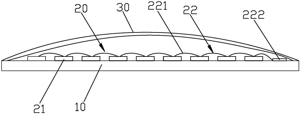
[0044] Please check figure 1 , a long-life LED lamp light-emitting unit, including a substrate 10 , a LED bare die part 20 and a fluorescent glue part 30 . The LED die portion 20 includes a plurality of LED die 21 and a circuit portion 22 electrically connected to the plurality of LED die 21 . The LED die 21 is fixed on the substrate 10 , and the substrate 10 and the fluorescent glue portion 20 are relatively fixed. . The plurality of LED bare die 20 emit blue light after being energized, and the blue light is converted into white light by the fluorescent glue part 20 and then irradiated to the outside. Of course, it can also be other colors. The fluorescent glue part 30 includes fluorescent powder and glue, and the glue and the fluorescent powder are mixed.

[0045] The substrate 10 is, for example, a transparent plate or an opaque plate. If the transparent plate is a glass plate, the front or back of the glass plate is coated with a reflective agent to form a reflective s...

Embodiment 2

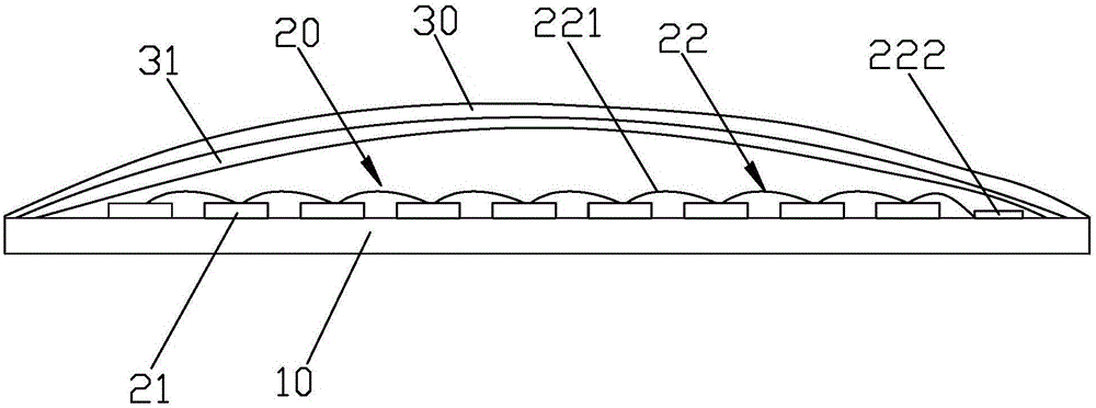
[0052] Please check figure 2 , it differs from the first embodiment in that: the fluorescent glue part layer 30 is coated on the inner surface or the outer surface of the lampshade 31 , and the lampshade 31 covers the LED bare die part 20 inside.

Embodiment 3

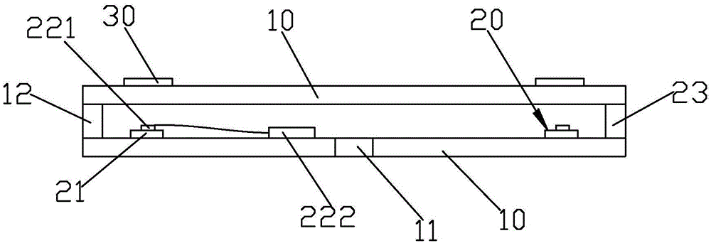
[0054] It differs from Embodiments 1 and 2 in that the above-mentioned circuit part is printed on the substrate for fixing the bare die to form a circuit board, that is, the above-mentioned bonding wire 221 and the joint part 222 are directly printed on the substrate, and the LED is bare. The crystal is fixed on the substrate, that is, it is electrically connected to the circuit part.


PUM


Abstract

The utility model provides a light-emitting unit of a long-service life LED lamp and a long-service life LED lamp. The light-emitting unit of the LED lamp comprises a base and LED naked crystals; the base comprises a plurality of transparent bearing substrates; the bearing substrates are arranged in parallel at intervals; a plurality of LED naked crystals are bound between every two adjacent bearing substrates; the plurality of LED naked crystals are connected by use of a lead; the base is coated with a fluorescent powder layer so that the light emitted by the LED naked crystals can be emitted out of the base after passing the fluorescent powder layer. The fluorescent powder layer can be disconnected at the connection points of a gold wire, and therefore, the tension to the gold wire due to cold shrinkage and thermal expansion of the fluorescent powder layer can be avoided, and the connection points can be protected against breakage due to the tension and then no arc is generated to act on charring the crystals. Due to multiple layers of the light-emitting unit, the uneven stress on the gold wire is reduced; due to the multi-layer luminous body and the multi-layer light-emitting unit, the heat dissipation area is increased under the circumstance of the same luminous efficiency, and therefore, the service life of the LED lamp is prolonged.

Description

technical field [0001] The present invention relates to a long-life LED lamp lighting unit. Background technique [0002] The existing LED lamp light-emitting unit includes a substrate, an LED bare die part and a fluorescent glue part, the LED bare die part includes a plurality of LED bare die and a circuit part electrically connected to the plurality of LED bare die, the LED bare die is fixed On the substrate, the fluorescent glue part is directly coated on the LED bare die part, and the plurality of LED bare die emit blue light after being energized. Since the fluorescent glue is directly coated on the LED bare die, when the fluorescent glue expands and contracts in heat, the electrical connection between the circuit part and the LED die will be torn off, or / and an arc will be generated. , causing the LED light-emitting unit to be scrapped, resulting in a short lifespan of the LED light-emitting unit. SUMMARY OF THE INVENTION [0003] The purpose of the present inventi...

Claims


Application Information

Patent Timeline
Patent Type & Authority Applications(China)
IPC IPC(8): F21S2/00F21V19/00F21V23/00F21Y101/02F21Y115/10
CPCH01L33/48H01L33/62F21V19/001F21V23/004
Inventor 吴鼎鼎
Owner 吴鼎鼎
Why Eureka
Try Eureka