A Solution and Visual Display Method of Custom Stress Function

A stress function and display method technology, applied in the direction of electrical digital data processing, special data processing applications, instruments, etc., can solve problems such as difficulties, high requirements for general finite element software operators, and inability to obtain technical support in time to achieve stress Precise, accurate nodal stress results

Inactive Publication Date: 2018-03-20
太原重工轨道交通设备有限公司 +2
View PDF3 Cites 0 Cited by
  • Summary
  • Abstract
  • Description
  • Claims
  • Application Information

AI Technical Summary

Problems solved by technology

Since the development of professional software has always lagged behind the development of related theories, and the secondary development of general-purpose finite element software has high requirements for operators, the stress state of components under different working conditions is analyzed according to specific theoretical requirements. Technical requirements for comprehensive analysis and visual display often cannot get corresponding technical support in time, which brings many difficulties to the work

Method used


Image

  • A Solution and Visual Display Method of Custom Stress Function
  • A Solution and Visual Display Method of Custom Stress Function
  • A Solution and Visual Display Method of Custom Stress Function

Examples


Embodiment Construction

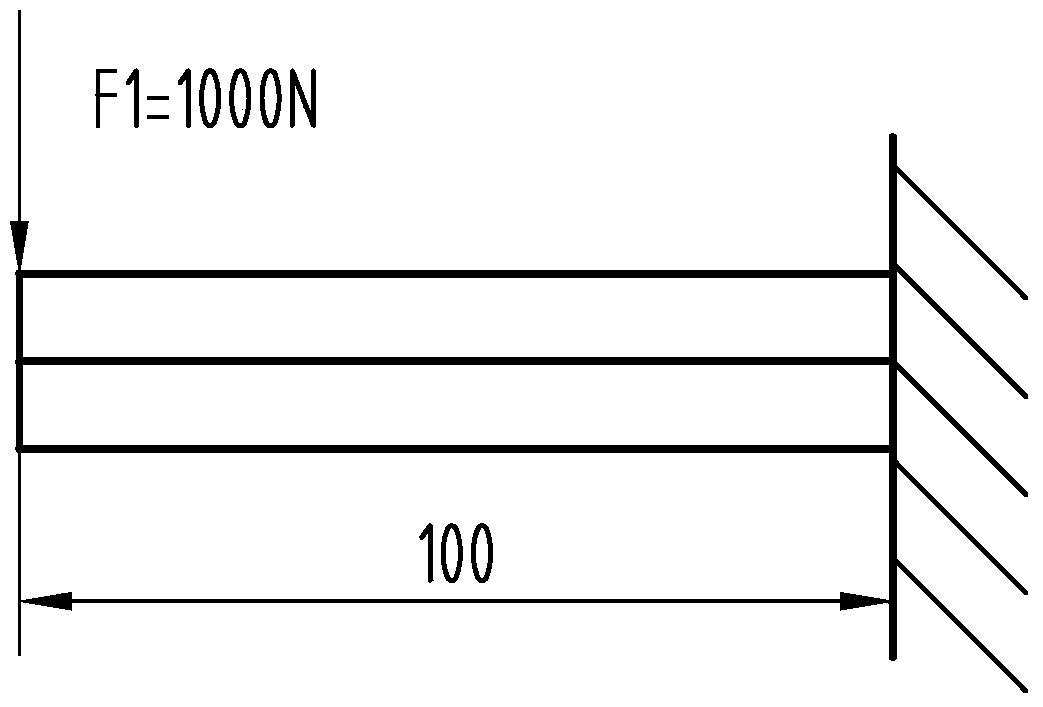
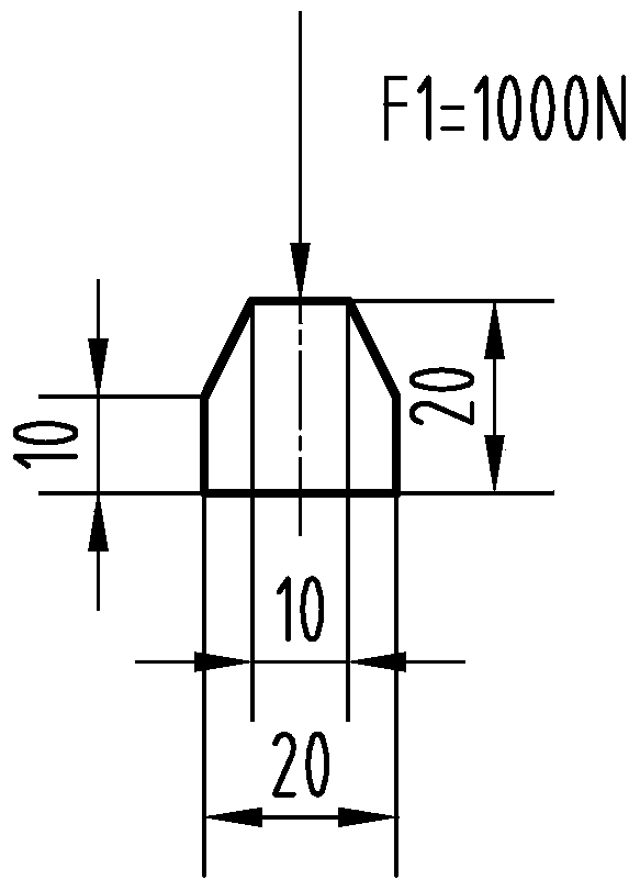
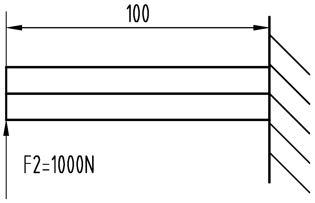
[0051] In order to describe the features of the present invention in detail, a preferred embodiment is described with accompanying drawings. figure 1 and figure 2 A schematic diagram of the force state of a cantilever beam with a special-shaped cross-section under working condition 1 is expressed, image 3 and Figure 4 It expresses the schematic diagram of the force state of the special-shaped cross-section cantilever beam under the working condition 2. The special-shaped cross-section cantilever beam shown is the same member, the shape and size are as shown in the figure (unit: mm), the material is 45 steel, and the elastic modulus of the material is 2.1 *10 5 MPa, yield strength σ s =360MPa, Poisson's ratio is 0.3. Working condition 1: one end is fixed, and the other end bears load F1; working condition 2: similar to working condition 1, one end is fixed, and the other end bears load F2; the specific theoretical requirements are as follows: First, the traditional equiv...


PUM


Abstract

A method for solving and visually displaying a self-defined stress function belongs to the technical field of finite element numerical simulation mechanical strength analysis. The present invention aims at the difficulties that may be encountered when general-purpose finite element software performs comprehensive analysis of specific theoretical requirements on the stress state of components under different working conditions, and is characterized in that: based on MSC.Marc / Mentat 2005 software, different working conditions For the finite element stress analysis results of the lower member, by extracting the stress component data of the unit integration points under various working conditions, set and calculate and solve the custom stress function data outside the general finite element software, and realize the custom stress function data by means of data replacement. Visualization of stress function data on MSC.Marc / Mentat 2005 finite element model. The advantages and positive effects of the present invention are that the realization method is simple and easy, the application range is wide, and the use limitation of professional software or secondary development can be avoided.

Description

technical field [0001] The invention belongs to the field of finite element numerical simulation mechanical strength analysis, and in particular relates to a method for solving and visually displaying a self-defined stress function. technical background [0002] The finite element method is a numerical simulation technology that uses mathematical approximation methods to simulate real physical systems, and can analyze field quantities such as stress, strain, and displacement of components under external load conditions. MSC.Marc / Mentat 2005 is an internationally famous general-purpose finite element analysis software. Among them, MSC.Marc 2005 is a finite element analysis module, and MSC.Mentat2005 is a visual interactive dialog interface for pre- and post-processing. The finite element analysis results of components can be displayed by means of lines, cloud diagrams, etc. [0003] In the field of mechanical strength analysis, the use of finite element method to calculate t...

Claims


Application Information

Patent Timeline
Patent Type & Authority Patents(China)
IPC IPC(8): G06F17/50
Inventor 王群娣田继红闫耀洲张河清魏华成候佩云李树林游晓红刘志祥李景丹郭丰伟
Owner 太原重工轨道交通设备有限公司
Why Eureka
Try Eureka