signal transmission system

A signal transmission system and electrical signal technology, applied in the field of signal transmission systems, can solve problems such as low signal transmission efficiency, and achieve the effects of saving transmission costs, improving signal transmission efficiency, and reducing transmission loss

Active Publication Date: 2018-06-01
HUANENG CLEAN ENERGY RES INST +1
View PDF4 Cites 0 Cited by
  • Summary
  • Abstract
  • Description
  • Claims
  • Application Information

AI Technical Summary

Problems solved by technology

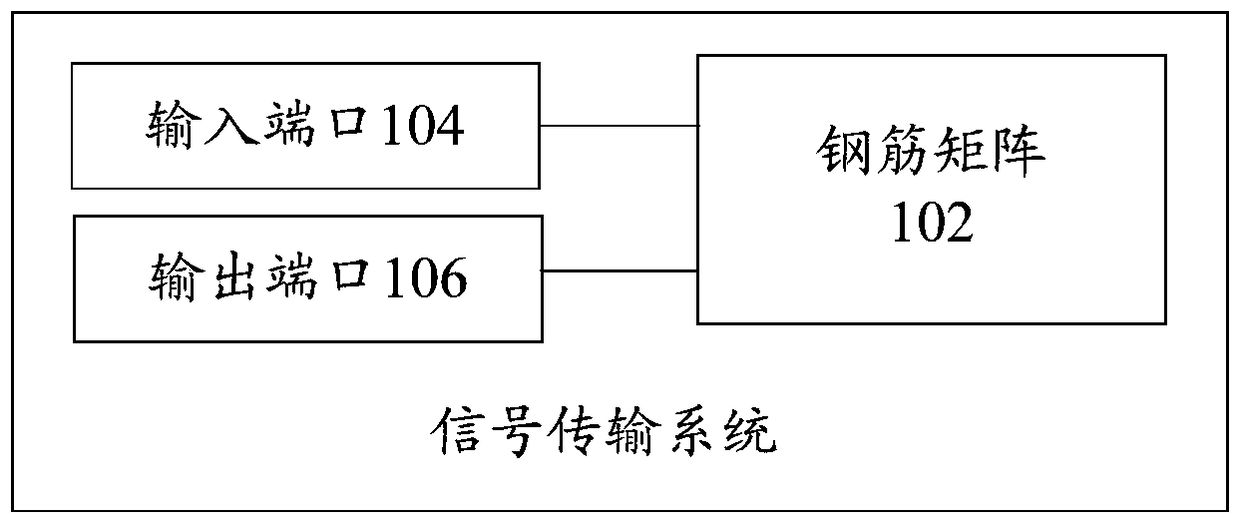
[0005] An embodiment of the present invention provides a signal transmission system to at least solve the technical problem of low signal transmission efficiency caused by the use of existing signal transmission methods

Method used


Image

  • signal transmission system
  • signal transmission system
  • signal transmission system

Examples


Embodiment Construction

[0023] In order to enable those skilled in the art to better understand the solutions of the present invention, the following will clearly and completely describe the technical solutions in the embodiments of the present invention in conjunction with the drawings in the embodiments of the present invention. Obviously, the described embodiments are only It is an embodiment of a part of the present invention, but not all embodiments. Based on the embodiments of the present invention, all other embodiments obtained by persons of ordinary skill in the art without making creative efforts shall fall within the protection scope of the present invention.

[0024] It should be noted that the terms "first" and "second" in the description and claims of the present invention and the above drawings are used to distinguish similar objects, but not necessarily used to describe a specific sequence or sequence. It is to be understood that the data so used are interchangeable under appropriate ...


PUM


Abstract

The invention discloses a signal transmission system. Wherein, the system includes: a steel bar matrix, deployed inside the building; an input port, connected to the steel bar matrix, for connecting the signal to be transmitted obtained from the sending device into the steel bar matrix, wherein the signal to be transmitted includes at least one of the following: The communication signal and the electric signal; the output port is connected with the reinforcement matrix, and is used to output the signal to be transmitted in the reinforcement matrix to the receiving device. The invention solves the technical problem of low signal transmission efficiency caused by adopting the existing signal transmission mode. The signal transmission through the steel matrix not only achieves the effect of improving the signal transmission efficiency, but also reduces the cable wiring in the building, so as to reduce the transmission loss and save the transmission cost.

Description

technical field [0001] The present invention relates to the technical field of engineering, in particular to a signal transmission system. Background technique [0002] Today, with the continuous development of energy technology, many distributed energy sources, such as rooftop photovoltaic power plants, will be converged to the control room through specific cables, and then utilized through operations such as inverter boosting. In general, the control room will be located on the floor. Due to the low output voltage of photovoltaic panels, the cables used for confluence need low resistance to meet low line loss. Therefore, the diameter of the cable is required to be several times or even higher than that of the mains cable. Dozens of times, this not only increases the transmission cost, but also destroys the original structure of the building due to the increased wiring of cables. [0003] In addition, most of the current buildings are reinforced concrete structures. While ...

Claims


Application Information

Patent Timeline
Patent Type & Authority Patents(China)
IPC IPC(8): H04B13/00
Inventor 赵志国秦校军王一丹邬俊波
Owner HUANENG CLEAN ENERGY RES INST
Why Eureka
Try Eureka