Neutral Valve Structure
a technology of neutral valves and valve bodies, applied in the direction of clutches, fluid couplings, gearing elements, etc., can solve the problems of enlargement, high production costs, and worsening and achieve the effect of preventing the deterioration of the transmission efficiency of the hst and low cos
- Summary
- Abstract
- Description
- Claims
- Application Information
AI Technical Summary
Benefits of technology
Problems solved by technology
Method used
Image
Examples
embodiment 1
[0072]Hereinafter, a first preferred embodiment of a neutral valve structure according to the present invention will be described referring to the accompanying drawings.
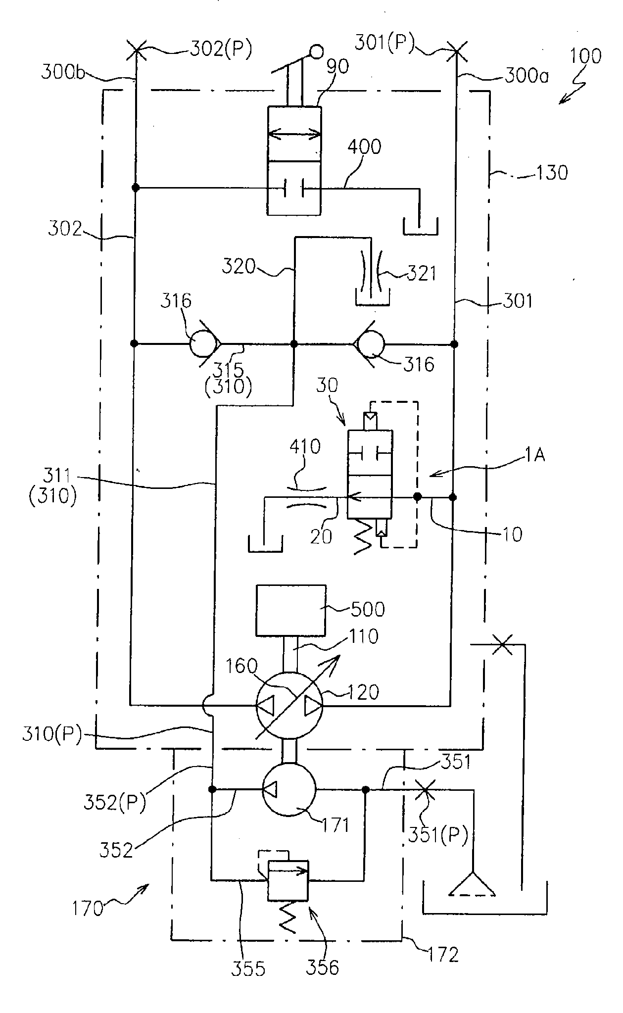
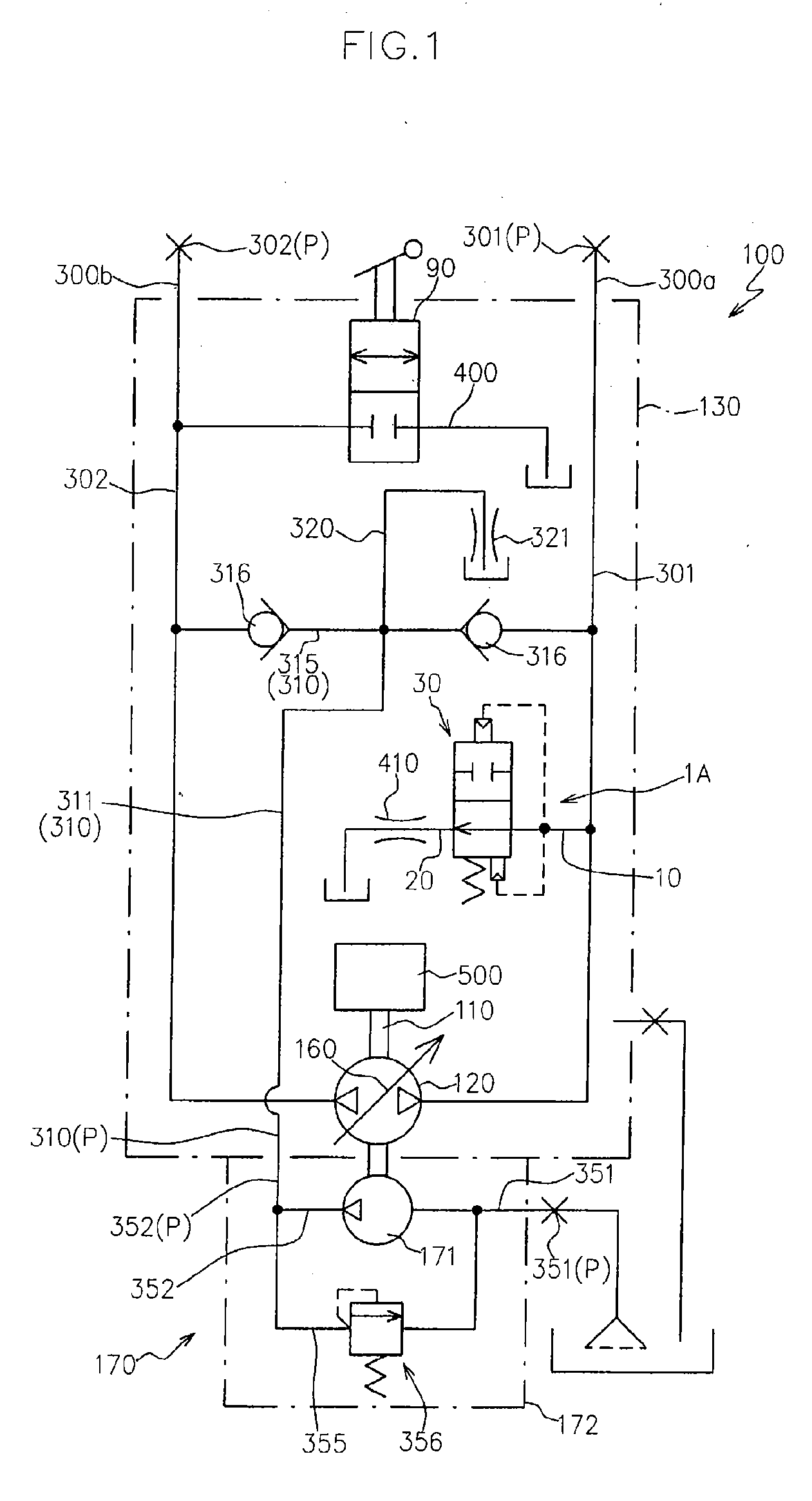
[0073]FIG. 1 shows a hydraulic circuit diagram of a hydraulic pump unit 100 to which a neutral valve structure 1A according to the present embodiment is applied.
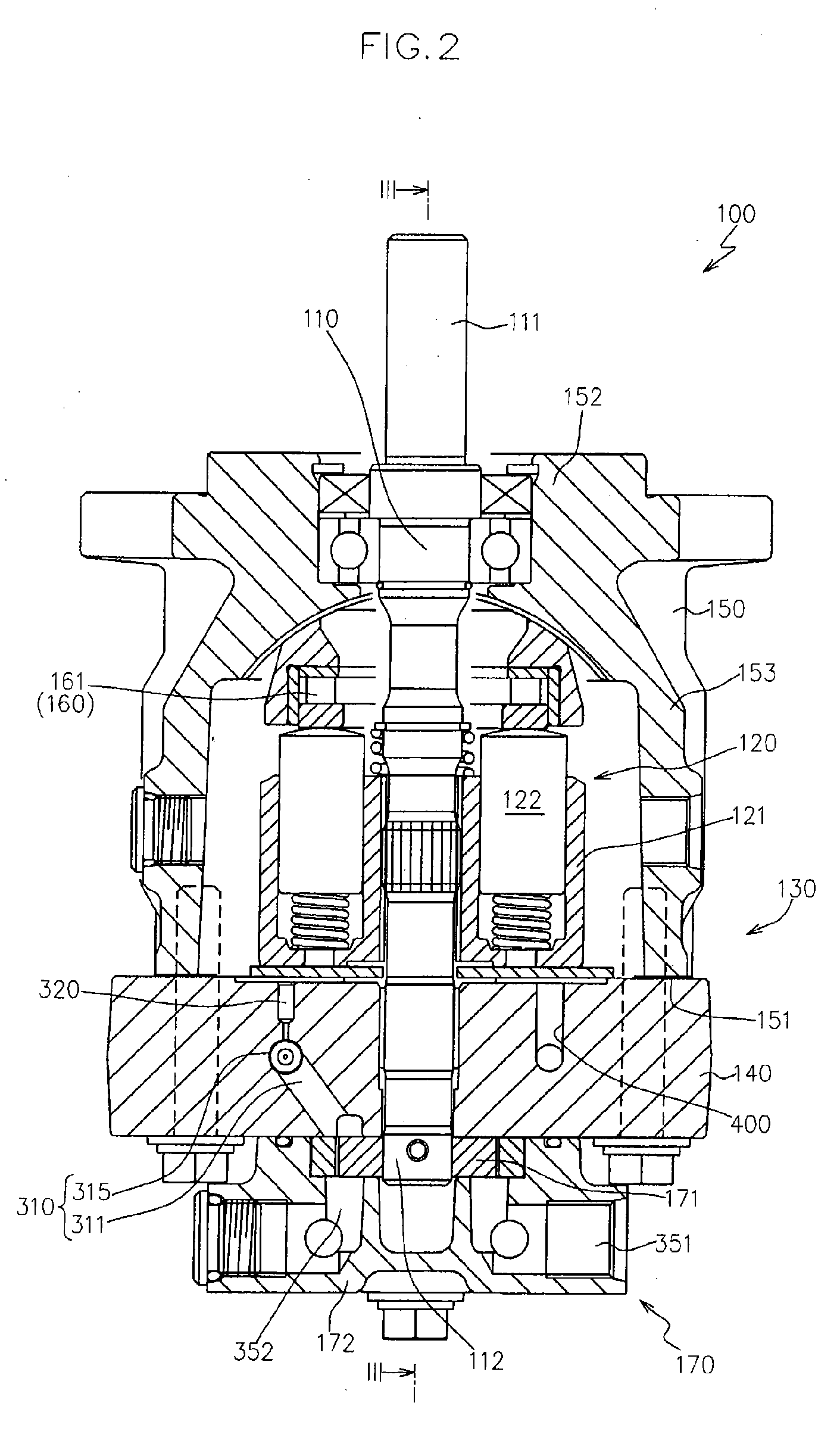
[0074]FIG. 2 shows a longitudinal sectional view of the hydraulic pump unit 100, and FIG. 3 shows a sectional view taken along line III-III in FIG. 2.
[0075]The hydraulic pump unit 100 is configured so as to be fluidly connected to a hydraulic motor unit (not shown) arranged away from the hydraulic pump unit with a space via a pair of first and second operation fluid lines 300a, 300b (see FIG. 1) so as to form an HST in cooperation with the hydraulic motor unit.
[0076]Specifically, as shown in FIGS. 1 to 3, the hydraulic pump unit 100 includes a pump shaft 110 operatively connected to a driving source 500, a hydraulic pump body 120 supported in a relatively non...
embodiment 2
[0143]Hereinafter, a second embodiment of a neutral valve structure according to the present invention will be described referring to the accompanying drawings.
[0144]FIG. 5 shows a cross sectional view of a port block 140B in a hydraulic pump unit to which a neutral valve structure 1B according to the present embodiment is applied.
[0145]The same members as those of the embodiment 1 are designated by the same reference numerals, and the repeated description is omitted.
[0146]As shown in FIG. 5, the neutral valve structure 1B according to the present embodiment includes the neutral valve 30A acting on the second operation passage 302 instead of the switch valve 90 in the neutral valve structure 1A according to the embodiment 1.
[0147]That is, the neutral valve structure 1B includes the neutral valve 30A attached from the base-end-side opening of the installation passage 10 so as to act on the first operation passage 301, and the neutral valve 30A attached from the tip-end-side opening o...
embodiment 3
[0151]Hereinafter, a third embodiment of a neutral valve structure according to the present invention will be described referring to the accompanying drawings.
[0152]In the present embodiment, explanation will be made with taking an example where the neutral valve structure according to the present invention is applied to an HST in which the hydraulic pump unit and the hydraulic motor unit are integrated.
[0153]FIG. 6 shows a hydraulic circuit diagram of an HST 200 to which a neutral valve structure 1C according to the present embodiment is applied.
[0154]The same members as those of the embodiments 1, 2 are designated by the same reference numerals, and the repeated description is omitted.
[0155]As shown in FIG. 6, the HST 200 includes the pump shaft 110, the hydraulic pump body 120, a hydraulic motor body 220 fluidly connected to the hydraulic pump body 120 via the pair of first and second operation fluid lines 300a, 300b, a motor shaft 210 rotated and driven by the hydraulic motor bo...
PUM
 Abstract
Description
Claims
Application Information
 - R&D
- Intellectual Property
- Life Sciences
- Materials
- Tech Scout
- Unparalleled Data Quality
- Higher Quality Content
- 60% Fewer Hallucinations
Browse by: Latest US Patents, China's latest patents, Technical Efficacy Thesaurus, Application Domain, Technology Topic, Popular Technical Reports.
© 2025 PatSnap. All rights reserved.Legal|Privacy policy|Modern Slavery Act Transparency Statement|Sitemap|About US| Contact US: help@patsnap.com


