Device for electrophoresis, device for transfer, device for electrophoresis and transfer, chip for electrophoresis and transfer, and method for electrophoresis, method for transfer, and method for electrophoresis and transfer

a technology which is applied in the field of electrophores methods for electrophoresis, transfer, and electrophoresis and transfer, etc., can solve the problems of electrophoresis speed decline, complex and skillful procedure, and the existence of a practical and easy-to-operate device for electrophoresis and transfer

Inactive Publication Date: 2013-01-17
SHARP KK +1
View PDF8 Cites 0 Cited by
  • Summary
  • Abstract
  • Description
  • Claims
  • Application Information

AI Technical Summary

Benefits of technology

[0017]A first feature of an example embodiment presented herein is to prevent decline in electrophoresis speed in an electrophoresis device including an electric conductor in an electrophoresis chamber.
[0100]According to this structure, it is possible to prevent decline in transfer efficiency by applying a suitable voltage depending on a molecular weight of each of the transfer target components same as the device for transfer of the present embodiment.

Problems solved by technology

As a result of study, however, the present inventors identified that the electrophoresis devices having an electric conductor in an electrophoresis chamber, such as the electrophoresis devices in the above documents have a problem of decline in electrophoresis speed.
However, a device disclosed in Japanese Publication for Unexamined Patent Application, Tokukai, No. 2000-28578 (date of publication: Jan. 28, 2000) still requires a complicated and skillful procedure such as a removal of gel after an electrophoresis.
However, a practical and easy-operation device for electrophoresis and transfer is not yet in existence.
Specifically, the electrophoresis device with the above structure failed to apply a voltage and migrate a sample in the process of electrophoresis.
However, the present inventors identified that transfer efficiency was declined in some samples in transferring them in gel to a membrane under a conventional transfer method.
In a conventional device for electrophoresis and transfer, however, the electrode, which is provided in the second voltage applying means for transferring separation target components in a first medium to a second medium, hampers the separation of the separation target components in the first medium.
Therefore, the conventional device was not useful.
In other words, the transfer efficiency declines when a voltage far from the suitable voltage is applied to the transfer target component.

Method used


Image

  • Device for electrophoresis, device for transfer, device for electrophoresis and transfer, chip for electrophoresis and transfer, and method for electrophoresis, method for transfer, and method for electrophoresis and transfer
  • Device for electrophoresis, device for transfer, device for electrophoresis and transfer, chip for electrophoresis and transfer, and method for electrophoresis, method for transfer, and method for electrophoresis and transfer
  • Device for electrophoresis, device for transfer, device for electrophoresis and transfer, chip for electrophoresis and transfer, and method for electrophoresis, method for transfer, and method for electrophoresis and transfer

Examples


example 1

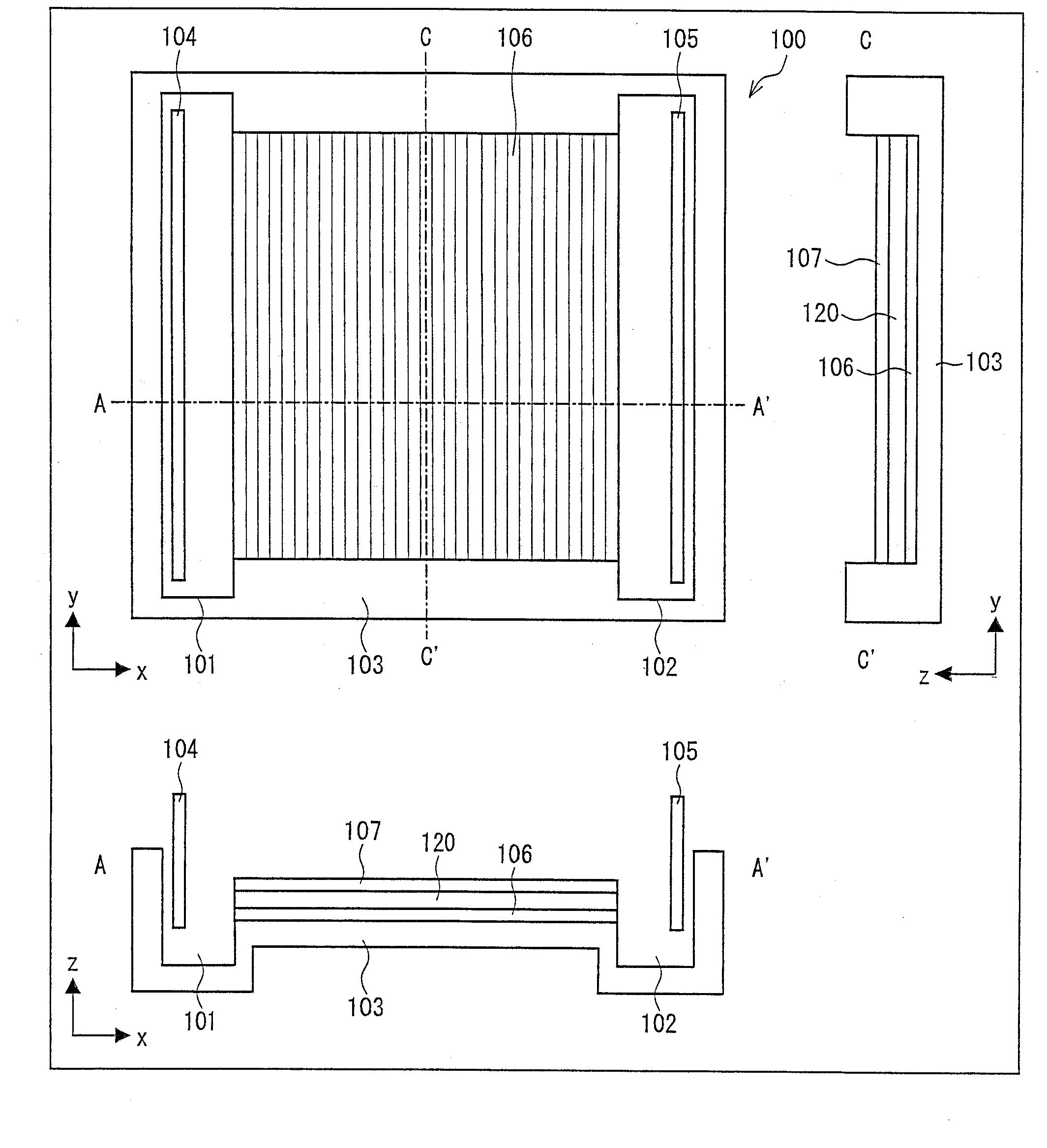
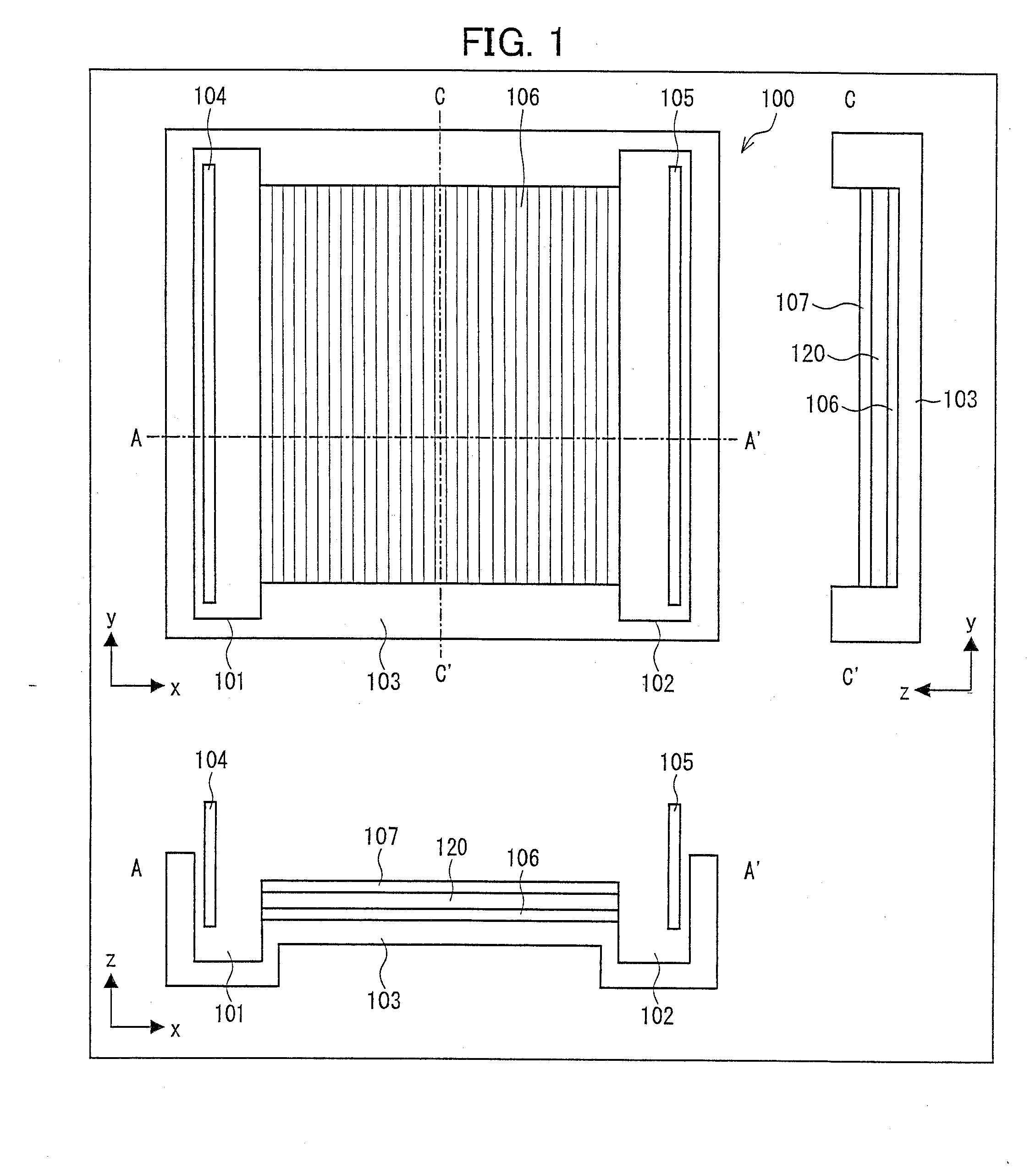
Making a Stripe Electrode

[0155]Cr binder was deposited on a 6 cm×5 cm glass plate 3 mm in thickness by a sputtering device and about 2000 Å Pt was also deposited. Then, a thickness of Pt electrode and a gap between Pt electrodes were created to be approximately 100 μm by a Dicing saw (Disco) with a blade 100 μm in thickness. In addition, two kinds of stripe electrode substrates, (i) a thickness of Pt wire and a gap between Pt wires were 100 μm and (ii) a thickness of Pt wire and a gap between Pt wires were 50 μm, were created by a CO2 laser carving machine under a following cutting condition, laser power 7%, process speed 6%, and 3000 Hz (FIG. 6). Note that the surface of the glass was little processed by a laser under the above condition.

example 2

Comparison of Substrates

[0156]A pair of 6 cm×5 cm gel plates (glass plate) sandwiching 1 mm spacer therebetween was placed in a gel-making container. A glass substrate was used as one side of the gel plates. As for the other side of the gel plates, a stripe electrode substrate plate in which a thickness of Pt wire and a gap between Pt wires were 100 μm, a substrate whose entire surface was covered by Pt, or a glass substrate (positive control) was used.

[0157]Next, after adding a processed resolving gel solution (13% acrylamide mixture (acrylamide:bisacrylamide=29.2:0.8), 378 mM Tris-HCl (pH 8.8), 0.05% APS, and 0.1% TEMED) up to 7 mm from the tip, water was added to form a water layer thereon. After the polymerization of the resolving gel solution, the water was removed, and then the processed and concentrated resolving gel solution (4% acrylamide mixture (acrylamide:bisacrylamide=29.2:0.8), 125 mM Tris-HCl (pH 8.8), 0.05% APS, and 0.2% TEMED) was added. Then, a sample comb was plac...

example 3

Studying a Method for Preventing the Generation of Air Bubbles

[0162]It was deduced that water electrolysis might occur between a pair of electrodes due to a potential difference between the electrodes (wires) of the stripe electrodes, thereby causing the air bubbles. Then, it was predicted that the generation of air bubbles could be prevented by controlling the potential difference between each pair of electrodes below 1V, decomposition voltage of water.

[0163]Then, with use of a stripe electrode substrate in which the thickness of Pt wire and the gap between Pt wires were 100 μm, the generation of air bubbles was monitored when altering applied voltage during SDS-PAGE. Table 1 shows the applied voltages, and calculated voltages between each pair of electrodes when the applied voltages were applied. Note that a voltage between a pair of electrodes was calculated by an applied voltage divided by the number of stripes.

TABLE 1VoltagebetweenTheeach pairNumberInitialDevice forofofElectric...


PUM

PropertyMeasurementUnit
voltageaaaaaaaaaa
voltageaaaaaaaaaa
voltageaaaaaaaaaa

Abstract

A device for electrophoresis applies a voltage to a medium in contact with a plurality of electric conductors so that a potential of adjacent conductors is within a certain range. This allows preventing decline in electrophoresis speed. A device for electrophoresis and transfer includes an electrode having a plurality of electrode regions being insulated one another and arranged in a specific direction. This allows providing a practical and easy-to-use device for electrophoresis and transfer. A device for transfer alters an applied voltage or applied voltage duration to a certain position to another position. This allows improving transfer efficiency.

Description

CROSS-REFERENCES TO RELATED APPLICATIONS[0001]This application is a divisional of U.S. patent application Ser. No. 12 / 130,691, filed May 30, 2008, and incorporated herein by reference; which Nonprovisional application claims priority under 35 U.S.C. §119(a) on Patent Applications No. 146215 / 2007, No. 146235 / 2007, and No. 146276 / 2007 each filed in Japan on May 31, 2007, the entire contents of which are hereby incorporated by reference.TECHNICAL FIELD[0002]The technology presented herein relates to devices for electrophoresis, transfer, and electrophoresis and transfer, and methods for electrophoresis, transfer, and electrophoresis and transfer.BACKGROUND AND SUMMARY[0003]In the life science field, electrophoresis is one of the significantly useful separating and analyzing techniques. It is used for separating biopolymers, such as protein, DNA, RNA, and the like. It is also possible to separate cells. In addition to a typical electrophoresis method with use of gel, a Capillary electro...

Claims


Application Information

Patent Timeline
Patent Type & Authority Applications(United States)
IPC IPC(8): B01D57/02
CPCG01N27/44704B01L3/50273
Inventor MARUO, YUJIUNUMA, YUTAKAHIRATSUKA, ATSUNORIKINOSHITA, HIDEKIYOKOYAMA, KENJISAKAIRI, KOJIAKUTSU, SATONARI
Owner SHARP KK
Why Eureka
Try Eureka