Synchronized code division multiplexing communication method and synchronized code division multiplexing communication system

a communication method and code division technology, applied in multiplex communication, data switching by path configuration, electrical devices, etc., can solve problems such as fall in transfer efficiency, and achieve the effect of preventing a fall in transfer efficiency

Inactive Publication Date: 2012-09-04
OKI ELECTRIC IND CO LTD
View PDF9 Cites 2 Cited by
  • Summary
  • Abstract
  • Description
  • Claims
  • Application Information

AI Technical Summary

Benefits of technology

[0011]The present invention is to provide a synchronized CDM communication method and synchronized CDM communication system that prevent a fall in transfer efficiency caused by the provision of a discovery time interval in transmission frames.

Problems solved by technology

Therefore, if such a time interval is provided in the transmission frame, a non-data transmission time interval in the transmission frame is extended, leading to a fall in transfer efficiency.

Method used


Image

  • Synchronized code division multiplexing communication method and synchronized code division multiplexing communication system
  • Synchronized code division multiplexing communication method and synchronized code division multiplexing communication system
  • Synchronized code division multiplexing communication method and synchronized code division multiplexing communication system

Examples


Embodiment Construction

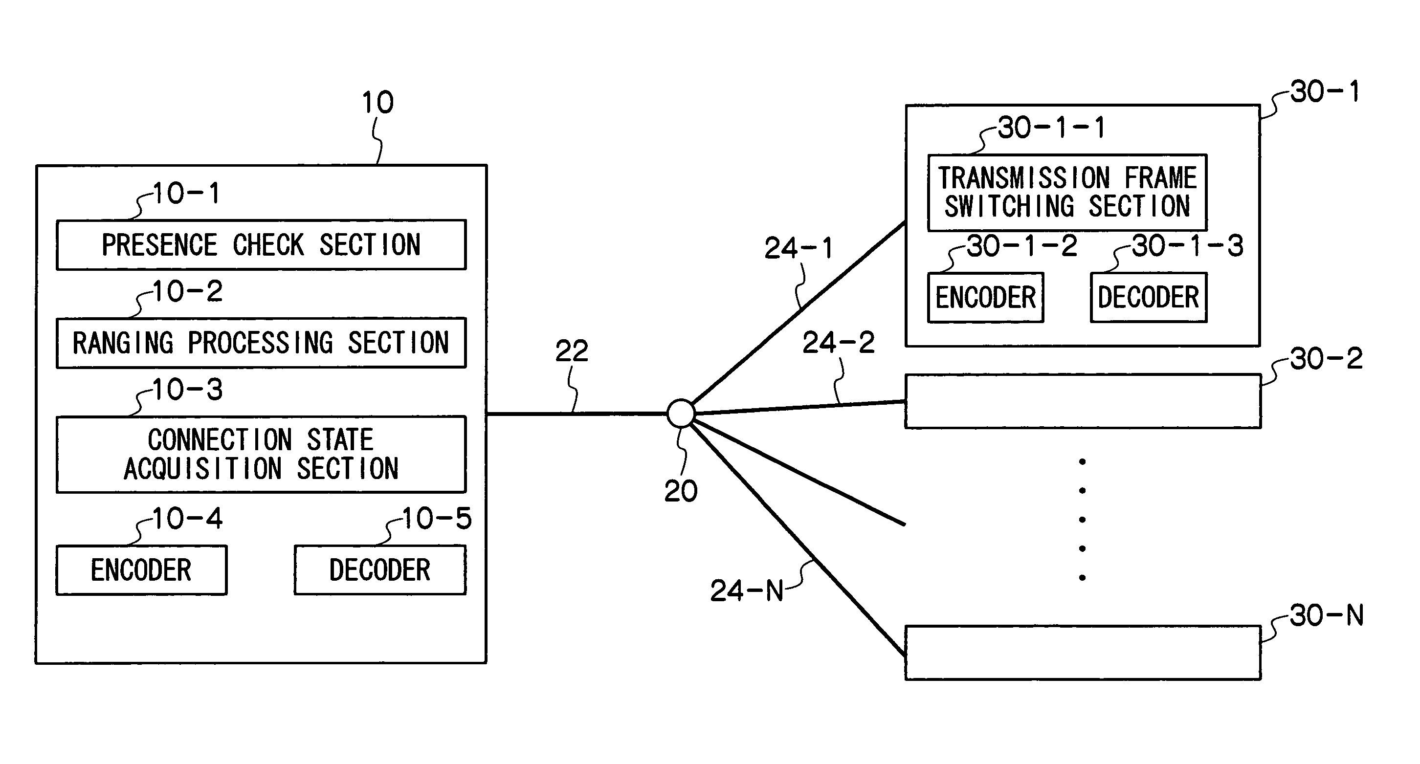
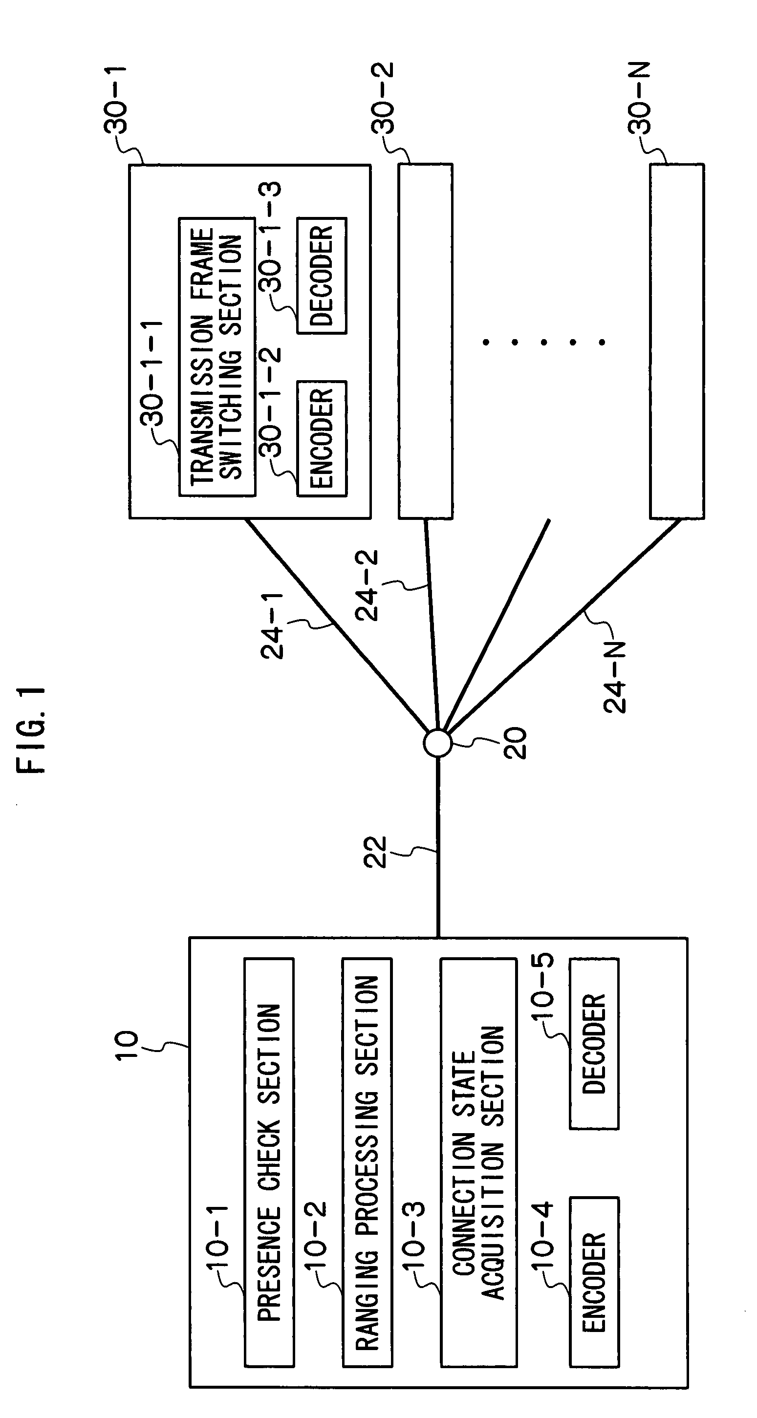
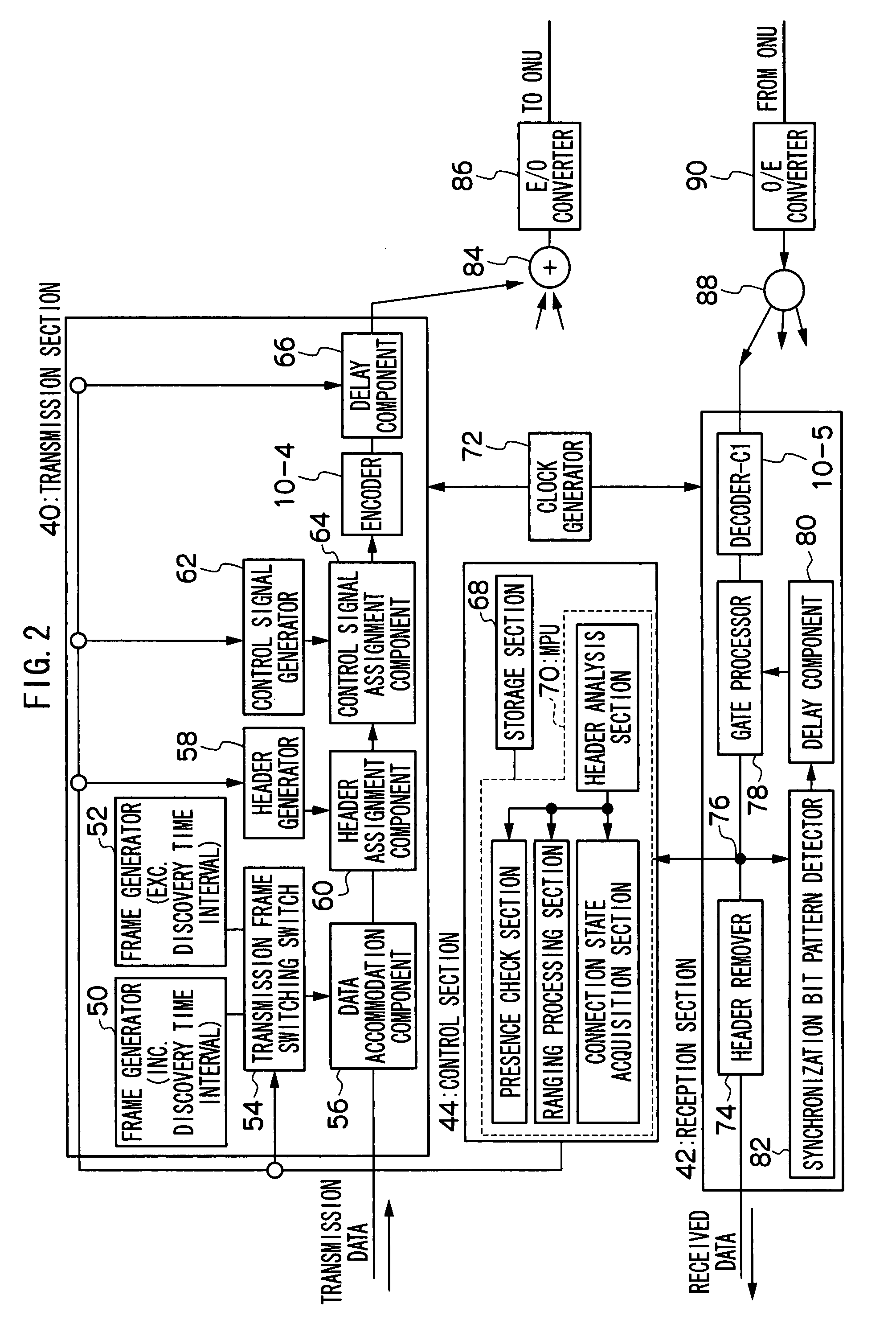
[0031]The inventors of the present invention have discovered a solution can be achieved if the configuration described below is concretely assembled. That is: preparing a transmission frame including a discovery time interval and a transmission frame not including a discovery time interval; communicating with the transmission frame not including the discovery time interval when a maximum number of ONUs that are physically connected to a central office are in states capable of communication with the central office; and communicating with the transmission frame including the discovery time interval when fewer than the maximum number of ONUs are in states capable of communication with the central office. According to a synchronized CDM communication method and a synchronized CDM communication system with such configurations, communication is performed with the transmission frame not including the discovery time interval when the maximum number of ONUs are in states capable of communica...


PUM


Abstract

A synchronized CDM communication system performs 1-to-N communication by CDM between a central office and first to N-th optical network units (ONU). The synchronized CDM communication system adds structural elements for realizing a connection state acquisition section to a conventional synchronized CDM communication system. A central office includes a presence check section, a ranging processing section and the connection state acquisition section. The presence check section checks the ONUs that are connected with the central office and the ONUs that are not connected. The ranging processing section performs transmission timing adjustments for the ONUs that are connected. The connection state acquisition section verifies whether all of ONUs are connected with the central office, and performs a discovery of a ONU, among the ONUs that were not connected at the time of the check, that has resumed participation in communication since the check ended.

Description

CROSS-REFERENCE TO RELATED APPLICATION[0001]This application claims priority under 35 USC 119 from Japanese Patent Application No. 2008-250107 filed on Sep. 29, 2008, the disclosure of which is incorporated by reference herein.BACKGROUND OF THE INVENTION[0002]1. Field of the Invention[0003]The present invention relates to a synchronized code division multiplexing (CDM) communication method and a synchronized CDM communication system that implement communication between a central office (an optical line terminal (OLT)) and plural optical network units (ONU) using synchronized code division multiplexing.[0004]2. Description of the Related Art[0005]An optical access network system which is configured by connecting a central office and plural ONUs together with a PON (a passive optical network) is a representative example of a communication system between a central office and plural ONUs. The central office is equipment installed at a business (referred to as a center node, a service no...

Claims


Application Information

Patent Timeline
Patent Type & Authority Patents(United States)
IPC IPC(8): H04J14/00H04J4/00H04B1/707H04B1/7073H04L12/44
CPCH04Q11/0067H04Q2011/0079H04Q2011/0088
Inventor SARASHINA, MASAHIRO
Owner OKI ELECTRIC IND CO LTD
Why Eureka
Try Eureka