
Automatic loading and unloading device

A technology of automatic loading and unloading, sliding fit, applied in the direction of assembling printed circuits with electrical components, electrical components, printed circuit manufacturing, etc., can solve the problems of insufficient rigidity, high labor intensity, low efficiency, etc., to improve the efficiency of loading and unloading. The effect of production efficiency

Active Publication Date: 2015-11-18
超音速人工智能科技股份有限公司
View PDF6 Cites 20 Cited by
  • Summary
  • Abstract
  • Description
  • Claims
  • Application Information

AI Technical Summary

Problems solved by technology

[0002] Flexible printed circuit board is a kind of highly reliable flexible printed circuit board made of polyimide or polyester film as the base material, also known as soft board or FPC, with high wiring density, low weight Light, thin, and good bendability, but the flexible circuit board also has the disadvantage of insufficient rigidity in some parts. At this time, it is necessary to use a reinforcing machine to attach the reinforcing sheet to these parts to increase the rigidity.
[0003] In the existing reinforcing machine, in order to avoid mechanical damage to the flexible circuit board, the loading operation of the flexible circuit board before attaching the reinforcing sheet and the unloading operation of the flexible circuit board after attaching the reinforcing sheet are all done manually , and the flexible circuit boards at the upper and lower material levels are stacked, and the adjacent flexible circuit boards are separated by partitions to prevent mutual collision and friction damage. Loading and unloading on the bulkhead is labor-intensive and inefficient, and it is easy to cause damage to the flexible circuit board due to misoperation

Method used


Image

  • Automatic loading and unloading device
  • Automatic loading and unloading device
  • Automatic loading and unloading device

Examples


Embodiment Construction

[0023] Below, in conjunction with accompanying drawing and specific embodiment, the present invention is described further:

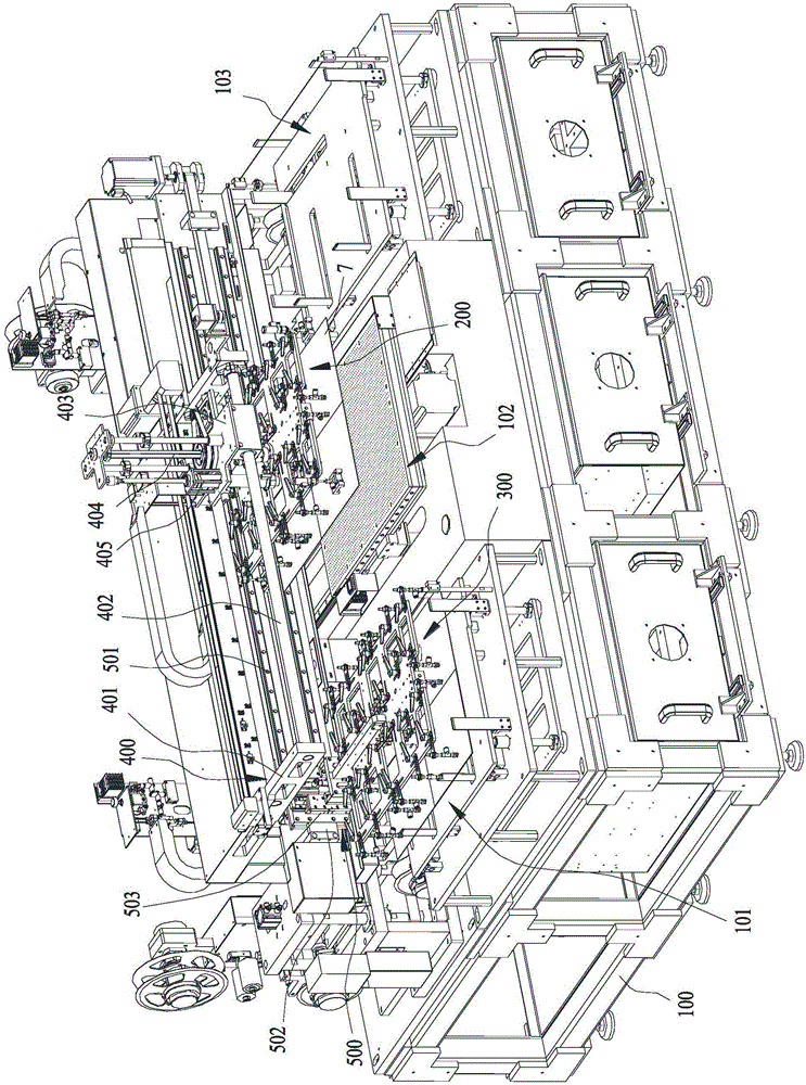
[0024] Such as figure 1 The shown automatic loading and unloading device includes a frame 100, a first suction cup device 200 for absorbing and grabbing a flexible circuit board 7, a second sucker device 300 for absorbing and grabbing a partition, a first sliding assembly 400 and For the second sliding assembly 500, the frame 100 is provided with a feeding table 101 for feeding the flexible circuit board 7 and the separator along the X-axis direction, and a mounting table for attaching a reinforcing sheet to the flexible circuit board 7 102 and the unloading platform 103 for the flexible circuit board 7 and the separator blanking; the first sliding assembly 400 and the second sliding assembly 500 are installed on the frame 100 and the heights are staggered, and the first suction cup device 200 passes through the second A sliding assembly 400 is slidabl...


PUM


Abstract

The invention discloses an automatic loading and unloading device. The device includes a frame, a first sucker device for absorbing and holding flexible circuit boards, a second sucker device for absorbing and holding separator plates, a first slide assembly, and a second slide assembly. The frame is sequentially provided, in an X-axis direction, with a loading bench for loading the flexible circuit boards and the separator plates, a sheet attaching bench for attaching reinforcing sheets to the flexible circuit boards, and an unloading bench for unloading the flexible circuit boards and the separator plates. The first slide assembly and the second slide assembly are arranged on the frame and positioned in a staggered manner, wherein one slide assembly is positioned above the other slide assembly. The first sucker device is in slide fit with the frame in the X-axis direction through the first slide assembly, and the second sucker device is in slide fit with the frame in the X-axis direction through the second slide assembly. The first sucker device and the second sucker device are both positioned above the loading bench, the sheet attaching bench and the unloading bench. The automatic loading and unloading device can automatically and stably load and unload the flexible circuit boards and the separator plates.

Description

technical field [0001] The invention relates to a processing technology of a flexible circuit board, in particular to an automatic loading and unloading device. Background technique [0002] Flexible printed circuit board is a highly reliable flexible printed circuit board made of polyimide or polyester film as the base material, also known as soft board or FPC, with high wiring density, light weight Light, thin, and good bendability, but the flexible circuit board also has the disadvantage of insufficient rigidity in some parts. At this time, it is necessary to use a reinforcing machine to attach reinforcing sheets to these parts to increase the rigidity. [0003] In the existing reinforcing machine, in order to avoid mechanical damage to the flexible circuit board, the loading operation of the flexible circuit board before attaching the reinforcing sheet and the unloading operation of the flexible circuit board after attaching the reinforcing sheet are all done manually ,...

Claims


Application Information

Patent Timeline
IPC IPC(8): H05K3/30
CPCH05K3/30H05K2203/0195
Inventor 张俊峰
Owner 超音速人工智能科技股份有限公司
Learn More