
Method and apparatus for use in removing a blade from a scalpel

A scalpel and blade technology, applied in the direction of anatomical instruments, etc., can solve the problems of unsafety, increased sharps damage, inability to provide safe and reliable blade removal mechanisms or devices, achieve safe and reliable structures, and reduce the risk of sharps damage , the effect of saving the amount of space

Inactive Publication Date: 2015-11-18
QLICKSMART PTY LTD
View PDF8 Cites 2 Cited by
  • Summary
  • Abstract
  • Description
  • Claims
  • Application Information

AI Technical Summary

Problems solved by technology

[0007] Such needle counters are often provided as separate items, thereby adding cost and complexity to the surgical procedure
[0008] Some needle counters incorporate scalpel blade removal mechanisms or mechanisms, but are generally considered unsafe because they do not provide safe and secure support for the blade removal mechanism or mechanism when in use
In particular, such needle counter / blade remover assemblies are not capable of resisting horizontal thrust and twisting forces during use of the device
As a result, the operator has to hold the assembly with one hand while manipulating the bladed scalpel with the other, increasing the likelihood of sharps injury

Method used


Image

  • Method and apparatus for use in removing a blade from a scalpel
  • Method and apparatus for use in removing a blade from a scalpel
  • Method and apparatus for use in removing a blade from a scalpel

Examples


Embodiment Construction

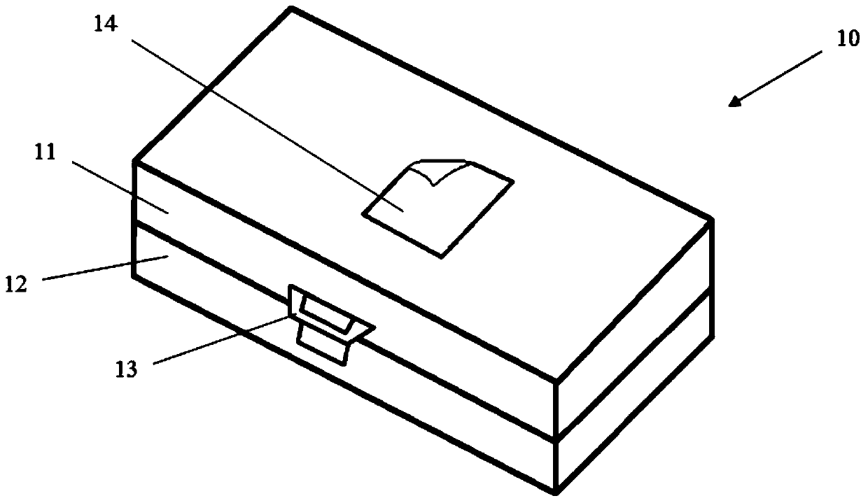
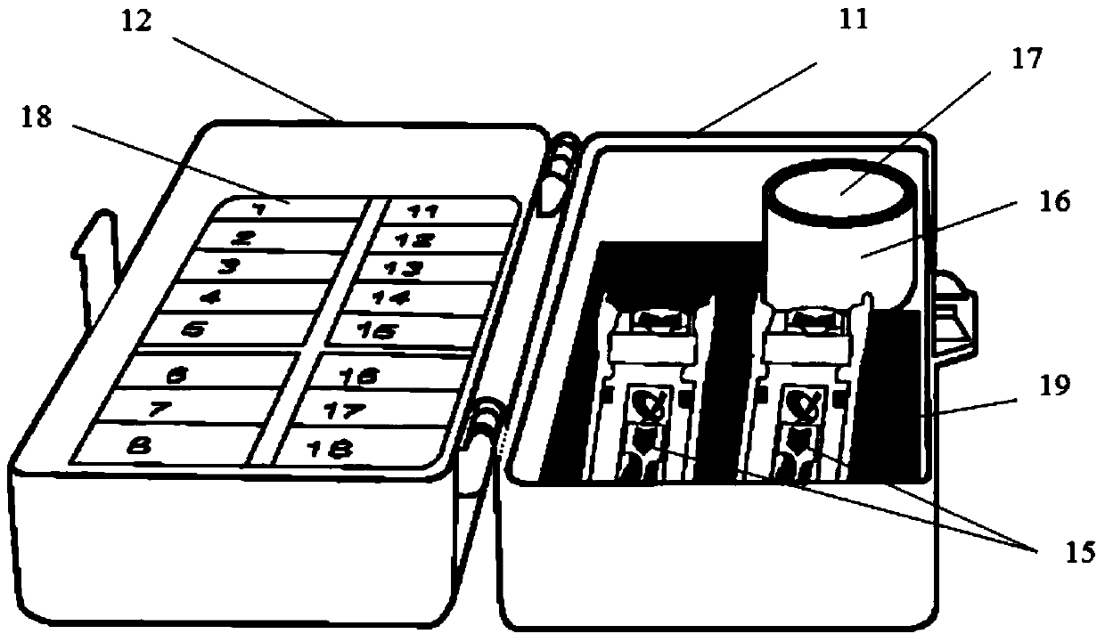
[0053] As shown in the drawings, one form of the present invention is a box body 10, which includes two dumpling parts 11, 12, which are releasably fixed by a buckle 13. Normally, the box body 10 is made of molded plastic material, and each hinge part 11, 12 is roughly in the form of a shallow rectangular tray.

[0054] A section of double-sided tape 14 is provided on the outside of the hinge part 11, and a section of double-sided tape (not shown) is also provided on the outside of the hinge part 12. Before placing the box 10 in place, the top layer of each piece of tape is peeled off to expose the adhesive surface. When the box body 10 is opened and placed in a desired position on a cloth towel, a tray or a table top, the adhesive tape 14 is used to assist in keeping the box body stable but detachable.

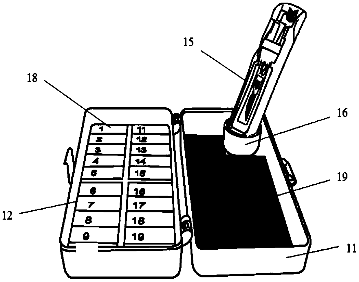
[0055] The hinge portion 11 may appropriately contain the required number of blade removers 15. These blade removers are preferably of the type described in the international pa...


PUM


Abstract

Apparatus is provided for safely removing a blade from a scalpel using a scalpel blade remover. The apparatus comprises a combination of a housing (10) having a formation defining a socket (17) of predetermined depth, and at least one elongate scalpel blade remover (15). The socket (17), which may be a tubular portion of circular cross section, is dimensioned to receive therein a lower portion of the blade remover (15) such that the blade remover is retained in an upright or inclined position in the socket when the housing is in an operative orientation. The blade remover (15) can be orientated within the socket (17) at a variable azimuth. The housing may be a case comprising two hinged parts (11,12), with the socket in one of the hinged parts, and a sharps holder (18) in the other hinged part.

Description

Technical field [0001] The invention relates to a method and device for removing a blade in a scalpel. [0002] In a specific embodiment, the invention relates to an assembly of this device and a needle counter. Background technique [0003] Any prior art mentioned in this specification is not and should not be regarded as an acknowledgement or suggestion, that is, prior art is a component of common knowledge in the field in any particular country. [0004] International patent application WO2004 / 093706 discloses a disposable scalpel blade removal device (hereinafter referred to as "blade remover"). The blade remover is elongated and has a slot suitable for receiving a scalpel blade. In use, the tang of the scalpel with the blade installed is inserted into the slot. When the tang is pushed into the device, the insertion of the tang drives the cam operating mechanism to separate the heel of the blade from the tang. When the tang is inserted to a predetermined degree, the blade is ...

Claims


Application Information

Patent Timeline
Patent Type & Authority Applications(China)
IPC IPC(8): A61B17/3217
CPCA61B17/3217
Inventor 基姆·奎克
Owner QLICKSMART PTY LTD
Learn More