
Pneumatic tire

A technology for pneumatic tires and treads, applied in pneumatic tires, reinforcement layers of pneumatic tires, motorcycle tires, etc., can solve problems such as impaired riding comfort, and achieve excellent riding comfort, handling stability and high-speed stability. Improves and realizes the effect of handling stability and high-speed stability

Active Publication Date: 2015-11-25
SUMITOMO RUBBER IND LTD
View PDF7 Cites 6 Cited by
  • Summary
  • Abstract
  • Description
  • Claims
  • Application Information

AI Technical Summary

Problems solved by technology

Therefore, when the end portion of the turnback portion is located near the flange, depending on the position of the end portion of the turnback portion relative to the flange, the entire sidewall portion may not be bent, which may affect ride comfort. damage

Method used


Image

  • Pneumatic tire
  • Pneumatic tire
  • Pneumatic tire

Examples


Embodiment 1

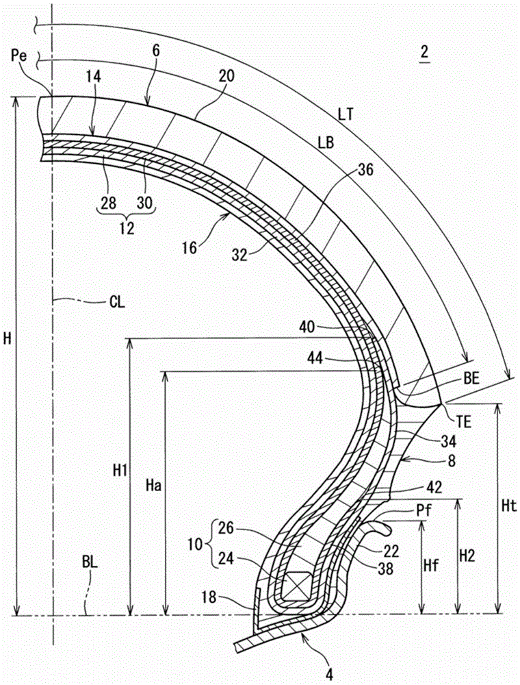
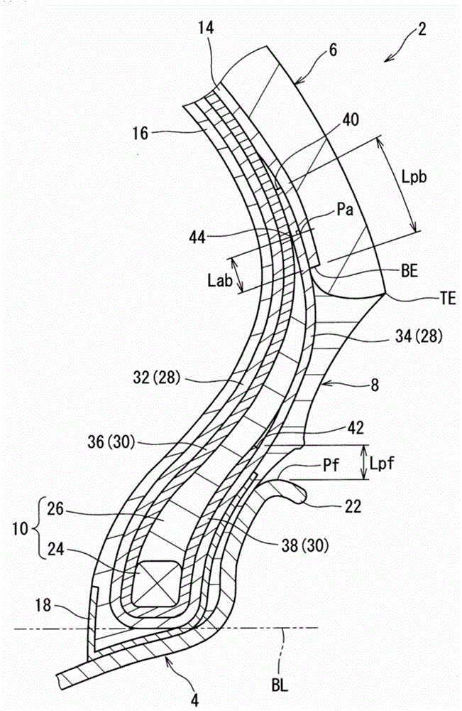
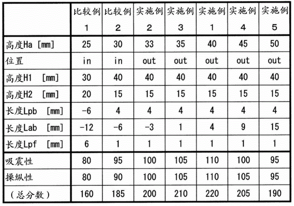
[0071] made Figure 1 ~ Figure 2 tires shown. The size of this tire is 120 / 70ZR17. The outer end of the apex is located radially outward from the end TE of the tread surface. This is indicated by "out" in the "Position" column of the table. The height Ha of the apex was 40 mm, the height H1 of the folded portion of the first ply was 40 mm, and the height H2 of the folded portion of the second ply was 15 mm. The length Lpb from the end BE of the reinforcing layer to the end of the folded-back portion of the first ply was 4 mm. The length Lab from the end BE of the reinforcing layer to the outer end of the apex is 4 mm. The radial length Lpf from the outer end Pf of the flange to the end of the turned-back portion of the second ply was 1 mm.

Embodiment 2~5 and comparative example 2

[0073] The tires of Examples 2 to 5 and Comparative Example 2 were obtained in the same manner as in Example 1 except that the height Ha was adjusted and the length Lab was set as shown in Table 1 below. In Comparative Example 2, the outer end of the apex rubber is positioned radially inward of the end portion TE of the tread surface. This is indicated by "in" in the "Position" column of the table.

Embodiment 6~11

[0077] Except for adjusting the height H1 and the height H2, and setting the length Lpb and the length Lpf as shown in Table 2 below, the rest were the same as in Example 1, thereby obtaining tires of Examples 6 to 11. .


PUM


Abstract

Pneumatic tire 2 for a motorcycle that exhibits enhanced steering stability and high-speed stability without reducing riding comfort. The tire 2 is provided with a tread 6, a pair of beads 10, a carcass 12 and a reinforcement layer 14. The tread 6 includes a tread surface 20 which makes contact with the ground. Each bead 10 is positioned on the radially inner side of the tread 6. The carcass 12 is bridged between the two beads 10. A reinforcement layer 14 is laminated on the carcass 12 on the radially inner side of the tread 6. Beads 10 each include a core 24 and an apex 26. The apex 26 extends from a core 24 in a radially outward direction. The outer edge 44 of teh apex 26 is positioned on the radially outer side of the tread edge (TE) of the tread surface 20.

Description

technical field [0001] The present invention relates to a pneumatic tire. Specifically, the present invention relates to a pneumatic tire mounted on a motorcycle. Background technique [0002] A motorcycle turns with the way its body leans. From the viewpoint of ease of turning, tires for motorcycles use treads with a small radius of curvature. [0003] In this tire, the equatorial surface portion (central portion) of the tread is in contact with the ground during forward running. During turning, the axially outer portion of the central portion touches the ground. Sometimes the rider repeatedly turns the motorcycle by leaning to the limit. This state is called "full-bankturning". During this extreme bending, the ends (shoulder portions) of the tread touch the ground. [0004] The performance of the motorcycle is significantly improved. Therefore, further improvement in performance is required also for tires mounted on motorcycles. [0005] For tires, handling stabili...

Claims


Application Information

Patent Timeline
Patent Type & Authority Applications(China)
IPC IPC(8): B60C9/08B60C9/18B60C15/06
CPCB60C9/18B60C5/00B60C15/0045B60C15/0603B60C2200/10B60C9/20B60C2015/009B60C2015/061
Inventor 大谷匡史
Owner SUMITOMO RUBBER IND LTD
Learn More