
Automatic-pressurizing seal butterfly valve

A self-filling, butterfly valve technology, applied in the direction of valve lift, valve details, valve devices, etc., can solve the problems of not widely used in practice, complex structure, high cost, etc.

Active Publication Date: 2015-11-25
东台市远洋船舶配件有限公司
View PDF6 Cites 0 Cited by
  • Summary
  • Abstract
  • Description
  • Claims
  • Application Information

AI Technical Summary

Problems solved by technology

However, this type of pressurized and sealed butterfly valve requires an external medium pressure system to maintain the sealing effect, so the structure is complex, the cost is high, and the actual application is not widespread

Method used


Image

  • Automatic-pressurizing seal butterfly valve
  • Automatic-pressurizing seal butterfly valve
  • Automatic-pressurizing seal butterfly valve

Examples


Embodiment Construction

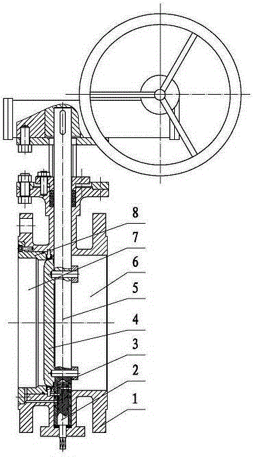
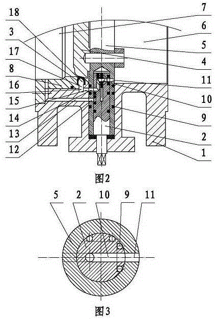
[0022] exist figure 1 In the self-pressurized sealing butterfly valve shown, the valve body 1 is a casting, and the right chamber of the valve body 1 is the valve body inlet 6, and the valve body inlet 6 communicates with the inlet pipe through the flange of the orifice. The left chamber of the valve body 1 is the valve body outlet cavity 7, the valve body outlet cavity 7 communicates with the liquid outlet pipeline through the flange of the orifice, and passes through the valve body on the upper side of the valve body 1 in the middle of the valve body 1 The valve stem 5 is installed on the wall, and the valve stem 5 is rotatably supported on the upper and lower valve body walls of the valve body 1. The valve stem 5 is driven by the worm gear mechanism outside the valve body 1 through the hand wheel, and the valve body 5 is fixedly connected with a valve. Disc 4, the valve disc 4 is disc-shaped, the valve disc 4 rotates with the valve stem 5 to open and close the valve, when...


PUM


Abstract

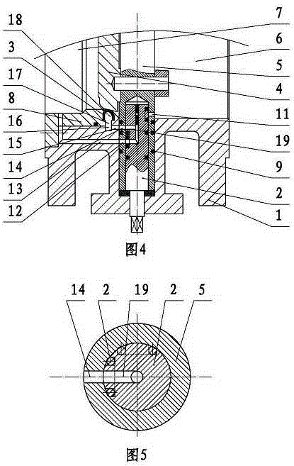
The invention discloses an automatic-pressurizing seal butterfly valve. The automatic-pressurizing seal butterfly valve comprises a valve body, a valve rod, a valve clack and a seal ring capable of forming a seal pair with the valve clack, wherein the seal ring is an annular seal ring with a pressurizing cavity and is mounted on the valve body through a side pressing cover; a valve body liquid passing hole communicated with the pressurizing cavity is formed in the valve body, and a valve body liquid leaking hole communicated with a valve body outlet cavity is further formed in the valve body; a rotatable control rod is arranged in the valve rod, a liquid feeding channel is formed in the valve rod and the control rod, and the valve body liquid passing hole can be communicated with a valve body inlet cavity through the liquid feeding channel; a liquid leaking channel is further formed in the valve rod and the control rod, and the valve body liquid passing hole can be communicated with the valve body liquid leaking hole through the liquid leaking channel. According to the automatic-pressurizing seal butterfly valve, the seal effect of a pressurizing butterfly valve can be achieved; besides, the structure is simple, and an external medium pressure system is not needed.

Description

Background technique [0001] The present invention relates to a valve, in particular to an improvement of the sealing structure of a butterfly valve. Background technique [0002] Butterfly valve is a kind of valve that uses the valve stem to drive the disc to turn back and forth about 90° to open, close or adjust the flow of medium. Its structure is simple, small in size, light in weight, low in material consumption, small in installation size, easy and fast in operation, and is one of the fastest-growing and most-used valve varieties. However, since the butterfly valve uses the sealing surface on the outer circumference of the disc and the sealing surface on the inner cavity of the valve to form a sealing pair, the elastic deformation of the elastic element in the sealing pair is used to ensure the sealing, so when the valve is opened and closed There is a large friction, and the sealing surface is easily damaged, resulting in seal failure; at the same time, the elastic el...

Claims


Application Information

Patent Timeline
IPC IPC(8): F16K1/226F16K27/02
CPCF16K1/226F16K27/02
Inventor 沈存斌司马瑞龙徐军
Owner 东台市远洋船舶配件有限公司
Learn More