System and method for measuring aspheric interference based on reference surface of spatial light modulator

A technology of spatial light modulator and interferometric measurement, which is applied to measurement devices, instruments, optical devices, etc., can solve the problems of low detection accuracy of compensator, high cost of compensator, mechanical phase shift error, etc., and achieves low requirements for manufacturing accuracy , improve stability and avoid the introduction of error sources

Active Publication Date: 2017-12-01
BEIJING INSTITUTE OF TECHNOLOGYGY
View PDF5 Cites 10 Cited by
  • Summary
  • Abstract
  • Description
  • Claims
  • Application Information

AI Technical Summary

Problems solved by technology

[0009] In view of the following technical problems in the existing interferometry technology: (1) high-precision compensators are expensive and difficult to manufacture,

Method used


Image

  • System and method for measuring aspheric interference based on reference surface of spatial light modulator
  • System and method for measuring aspheric interference based on reference surface of spatial light modulator
  • System and method for measuring aspheric interference based on reference surface of spatial light modulator

Examples


example 1

[0038] The specific parameters of the aspheric surface measured in this example are as follows: diameter 50.8mm; aspheric surface coefficient -1.01; quartic term coefficient of surface shape 1.27×10 -8 .

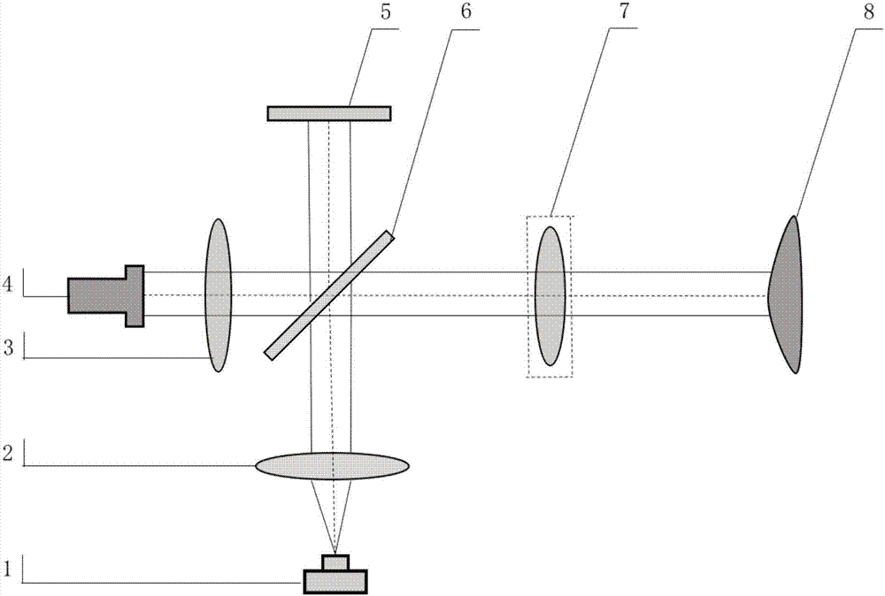
[0039] The aspheric interferometry system based on the spatial light modulator reference surface disclosed in this example includes a laser 4, a collimating objective lens 3, a beam splitter 6, an SLM reference mirror 5, an aspheric surface to be measured 8, an imaging objective lens 2, and a CCD detector 1 .

[0040] The optical path of the above-mentioned aspheric interferometry system is:

[0041] The parallel light formed by the laser beam emitted by the laser 4 is projected onto the beam splitter 6 after being collimated by the objective lens 3 , and then split into two beams after passing through the beam splitter 6 . A light beam returns to the beam splitter 6 after being passed through the SLM reference mirror 5. This beam is defined as a reference beam. In the ref...

example 2

[0052] The specific parameters of the aspheric surface measured in this example are as follows: diameter 50.8mm; vertex curvature radius -8000mm; aspheric surface coefficient -1.01; quadratic coefficient of surface shape 4.50×10 -5 ;Quaternary term coefficient 1.55×10 -8 ;Sixth order coefficient 1.1×10 -10 .

[0053] The aspheric interferometry system based on the spatial light modulator reference surface disclosed in this example includes a laser 4, a collimating objective lens 3, a beam splitter 6, an SLM reference mirror 5, a compensator 7, an aspheric surface to be measured 8, an imaging objective lens 2, CCD detector 1.

[0054] The optical path of the above-mentioned aspheric interferometry system is:

[0055] The parallel light formed by the laser beam emitted by the laser 4 is projected onto the beam splitter 6 after being collimated by the objective lens 3 , and then split into two beams after passing through the beam splitter 6 . A light beam returns to the beam ...


PUM

PropertyMeasurementUnit
Diameteraaaaaaaaaa

Abstract

The invention proposes a system and a method for measuring aspheric interference based on reference surface of a spatial light modulator, relating to an interferometry system and an interferometry method for measuring the aspheric surface shape and belonging to the field of photoelectric detection. The measuring system of the invention comprises a laser, a collimating objective, a spectroscope, a reference lens, a compensator, a to-be-measured aspheric surface, an imaging objective and a CCD detector. The SLM is used as the reference lens for an aspheric interferometry system, defined as an SLM reference lens. The present invention also discloses a measuring method using an aspheric interferometry system. The technical problem to be solved in the present invention is to generate a non-planar wavefront equal to a partially compensated aspheric wavefront and achieves zero-interference measurement. While the system and the method inherit the advantages of the partially compensating method that requires lower precision on the designing and manufacturing of the compensator, the advantage of high accuracy of the zero-compensation interferometry method is also maintained. In addition, it is possible to avoid the introduction of mechanical phase shift error in a traditional interferometry system.

Description

technical field [0001] The invention relates to an interferometric measurement system and method for measuring the shape of an aspheric surface, belonging to the field of photoelectric detection. Background technique [0002] Aspheric surface is a general term for curved surfaces that deviate from spherical surfaces. The use of aspheric optical components in the optical system can not only increase the freedom of optical design, but also help to correct aberrations, improve image quality, and improve the performance of the optical system. It can also reduce the number and weight of optical components, simplify the structure of the instrument, and greatly reduce the system size and weight, reducing cost. However, due to the difficulty of aspheric surface detection, the processing accuracy of aspheric surfaces has not been guaranteed. Research on high-precision, simple and practical aspheric surface detection technology is still a major problem in the field of optical detecti...

Claims


Application Information

Patent Timeline
IPC IPC(8): G01B9/02
Inventor 郝群宁妍胡摇张馨木
Owner BEIJING INSTITUTE OF TECHNOLOGYGY
Why Eureka
Try Eureka