On-line detection device and process method of air foam flooding produced gas

An air foam and detection device technology, applied in the field of oil extraction, can solve problems such as hidden safety hazards, different levels of proficiency in instruments, and heavy labor, so as to ensure smooth production, improve research level and application effects, and ensure safe production.

Active Publication Date: 2016-10-19
PETROCHINA CO LTD
View PDF5 Cites 0 Cited by
  • Summary
  • Abstract
  • Description
  • Claims
  • Application Information

AI Technical Summary

Problems solved by technology

[0008] Due to the large number of oil wells in the test area and the mountainous area, the labor load is too large, so the test work cannot be carried out normally; in addition, due to the frequent change of test personnel, different people have different levels of proficiency in the instruments, resulting in differences in test results. likely to cause safety hazards

Method used


Image

  • On-line detection device and process method of air foam flooding produced gas

Examples


Embodiment 1

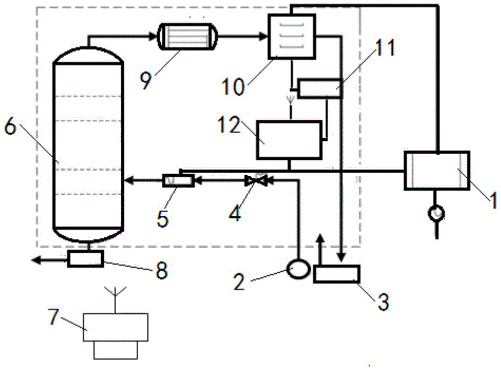
[0026] Embodiment 1: as figure 1 As shown, an air foam flooding produced gas online detection device,

[0027] 1. Gas detection device:

[0028] Mainly by O with data display function 2 , CO, CO 2 It is composed of a combustible gas detection transmitter 10, a solenoid valve 8, a GPRS data acquisition and control module, an industrial control computer, and the like.

[0029] 2. Gas collection and processing device:

[0030] A gas collection, control and processing device consisting of a flow controller 4, a solenoid valve 8, a gas-liquid separator (with pressure control function), and a filter. Provide the clean produced gas to the gas detector with the allowable flow rate and pressure to avoid damage to the detector and connecting pipelines, and ensure the safe and smooth operation of the detection device.

[0031] 3. GPRS network and software data acquisition, processing, analysis and control device:

[0032] Collect and display the parameters of gas components produce...

Embodiment 2

[0050] Embodiment 2: as figure 1 As shown, an air foam flooding produced gas online detection device,

[0051] (1) The linear distance between the gas detection cabinet and the oil-gas separator is 20-30m;

[0052] (2) The straight-line distance between the gas detection cabinet and the vent point is 5m, and the vent end is raised by 3m (protected by a rainproof cap);

[0053] (3) Gas sampling pipelines and venting pipelines are made of galvanized pipes, and the connections with the cabinets are connected by threads (the materials and joints in the cabinets are stainless steel);

[0054] (4) The gas transmitter has dual modes of remote transmission and display;

[0055] (5) Sampling pipelines and venting pipelines are used for thermal insulation treatment, and DN15 galvanized pipes and DN25 galvanized pipes are used respectively;

[0056] (6) 220VAC adopts aviation plug connection mode, if it is not equipped with a heating belt, the power is 220V / 10A; otherwise, 220V / 50A po...


PUM


Abstract

An air foam flooding produced gas on-line inspection apparatus and process, and belongs to the technical field of oil extraction. An explosion-proof power supply 1 is connected to and provides power for a flow controller 4, a solenoid control valve 5, an O2, CO, CO2 and combustible gas detection transmitter 10, a GPRS network device 12 and all pipe insulation heating devices. A wellhead casing head gas is introduced into a flow controller 4 through a gas introduction pipe; the other end of the flow controller 4 is connected to the solenoid control valve 5 via line; the other end of the solenoid control valve 5 is connected a buffer tank 6 via line; the bottom of the buffer tank 6 is connected to an electromagnetic valve 8; a pipe on the upper part of the buffer tank 6 is connected to a gas filter 9; the other end of the gas filter 9 is connected to the O2, CO, CO2 and combustible gas detection transmitter 10 via a pipe; the O2, CO, CO2 and combustible gas detection transmitter 10 is connected to a data acquisition unit 11; the data acquisition unit 11 collects and transmits the test data to the GPRS network device 12 and transmits the data to the a computer software apparatus 7 in a control room.

Description

technical field [0001] The invention relates to an on-line detection device and a process method for air foam flooding produced gas, belonging to the technical field of oil recovery. Background technique [0002] The air foam flooding technology is to use a blower to inject a certain amount of air into the oil layer through the injection well. Due to the existence of natural fractures, bedding and vertical fractures formed by fracturing in the formation, gas channeling is prone to occur; or, due to the long-term injection of water along the large The channel flow further scours the formation, increases the heterogeneity, and is prone to gas channeling; these unfavorable factors will cause the injected gas to be produced from the oil well prematurely; because the air contains a certain amount of oxygen, it is easy to produce oxygen from the oil well. Severe corrosion occurs to oil production equipment, especially when the oxygen concentration reaches a certain amount, it is p...

Claims


Application Information

Patent Timeline
Patent Type & Authority Patents(China)
IPC IPC(8): G01N33/00
Inventor 李安琪赵继勇高春宁李兆国胡建国陈辉商永滨孟浩曲本全张康王靖华陈杰李言冯白羽庞岁社
Owner PETROCHINA CO LTD
Why Eureka
Try Eureka