Inorganic polarizing plate and production method thereof

A polarizing plate, inorganic technology, applied in optics, polarizing elements, optical elements, etc., can solve the problem of no light source and so on

Active Publication Date: 2020-02-07
DEXERIALS CORP
View PDF9 Cites 0 Cited by
  • Summary
  • Abstract
  • Description
  • Claims
  • Application Information

AI Technical Summary

Problems solved by technology

However, there is such a problem that when trying to make the spacing between the metal lines 100nm, there is no light source available for practical use

Method used


Image

  • Inorganic polarizing plate and production method thereof
  • Inorganic polarizing plate and production method thereof
  • Inorganic polarizing plate and production method thereof

Examples


example

[0174] Examples of the present invention will be described below, but these examples should not be construed as limiting the scope of the present invention.

[0175] Electromagnetic field simulations were performed by rigorous coupled wave analysis using a Gsolver grating analysis simulator (Grating Solver Development Co.).

[0176] (simulation 1)

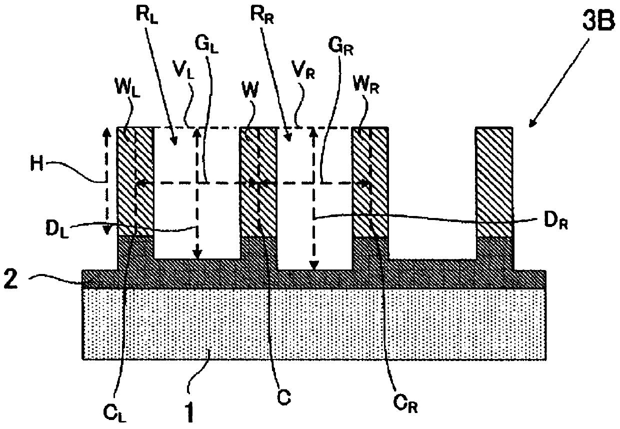
[0177] confirmed that due to changing the gap (G L ) and gap (G R ) The change in light transmittance caused by the difference between. Specifically, by changing the metal wire (W) and the metal wire (W L ) and the gap between the metal wire (W) and the metal wire (W R ), where these metal lines are composed of aluminum, to simulate the change in light transmittance.

[0178] A schematic cross-sectional view of the structure of the wire grid layer used for this simulation is in Figure 3A Presented in , simulated conditions and decrease in transmittance (decrease in transmittance) are presented below.

[0179] Table 1-1

[...


PUM

PropertyMeasurementUnit
thicknessaaaaaaaaaa
thicknessaaaaaaaaaa

Abstract

An inorganic polarizing plate, containing: substrate transparent to light of bandwidth for use; and wire grid layer containing metal wires aligned on the substrate with gaps shorter than wavelength of the light, the plate satisfying formulae (1) to (3): 0 nm<(DR−DL)  Formula (1); 0 nm<|GR−GL|  Formula (2); and 0.90≦̸SR / SL≦̸1.30  Formula (3), where DL is distance along thickness direction of the substrate in region RL between one metal wire W and metal wire WL next to W in the wire grid layer, and DR is distance along the thickness direction of the substrate in region RR between W and metal wire WR provided next to W and at opposite side to side where WL is provided; GL is gap between W and WL, and GR is gap between W and WR; and SL is ratio of DL to GL, and SR is ratio of DR to GR.

Description

technical field [0001] The invention relates to an inorganic polarizing plate and a production method thereof. Background technique [0002] Polarizers, which polarize light in a specific direction and pass only polarized light, are used in liquid crystal displays. [0003] As for the polarizing plate, a polarizing film is widely used, which is prepared by adsorbing an iodine compound on a polyvinyl alcohol (PVA) film, and stretching and orienting the resulting product, thereby exhibiting linear dichroism of absorption of visible light . This polarizing film is sandwiched on both sides with a transparent film such as triacetyl cellulose (TAC) to ensure mechanical strength, heat resistance, and moisture resistance, and is treated with a non-slip and abrasion-resistant coating on it to prevent scratches, or dust deposits. [0004] Among the light rays incident on the polarizing film, the polarized components of the light rays not passing through the polarizing film are abso...

Claims


Application Information

Patent Timeline
Patent Type & Authority Patents(China)
IPC IPC(8): G02B5/30
CPCG02B5/3058C23C16/44C23C16/45525
Inventor 花岛直树
Owner DEXERIALS CORP
Why Eureka
Try Eureka