High Density Splice Fiber Distribution Tray

A high-density, splicing disk technology, applied in light guides, optics, instruments, etc., can solve the problems of poor versatility, single function, and small storage space, and achieve the effects of small space occupation, expanded capacity, and strong versatility

Inactive Publication Date: 2018-04-06
宁波隆兴电信设备制造有限公司 +1
View PDF9 Cites 0 Cited by
  • Summary
  • Abstract
  • Description
  • Claims
  • Application Information

AI Technical Summary

Problems solved by technology

The distribution cable fusion storage integrated tray structure is divided into 3 independent storage areas, which is very convenient to take out and store the pigtails without affecting the 8 pigtails in the other 2 areas, which is very beneficial to the protection of the pigtails; 3 The pigtails in the independent storage area have corresponding independent pigtail channels in the process of taking out and using, without interfering with each other, it is very convenient to find and arrange the pigtails; the 4 pigtails form a whole through the rotating mooring plate, which is very convenient for the pigtails For coiling and taking out, a Chinese utility model patent "A Small Intelligent Welding and Fitting Integrated Tray Device" with patent number ZL201320852864.7 (notification number CN 203705682U) also discloses a pallet device with an upper and lower two-layer structure , including a tray cover, a fiber splicing tray and a fusion splicing chip; the splicing tray is arranged on the tray base, the tray cover is arranged on the splicing tray, and the fusion chip is arranged under the tray cover and on the splicing tray, In this way, the fiber storage and the fusion fiber are two independent spaces, which makes the storage space larger, and at the same time prevents the fiber output, cable input, fiber storage and fusion from being disturbed. However, during use, the opening of the integrated tray Only one type of pigtail adapter mating hole is suitable, and its function is single, and its versatility is poor, which will bring troubles to on-site construction; Higher requirements have been put forward for the convenience of distribution cables, and there are problems such as complex placement structure, small storage space, or restrictions on the position of fiber outlet and cable entry, or inconvenient search and arrangement of melting and storage pigtails for distribution cable fusion and storage units. , need further improvement

Method used


Image

  • High Density Splice Fiber Distribution Tray
  • High Density Splice Fiber Distribution Tray
  • High Density Splice Fiber Distribution Tray

Examples


Embodiment Construction

[0027] The present invention will be further described in detail below in conjunction with the accompanying drawings and embodiments.

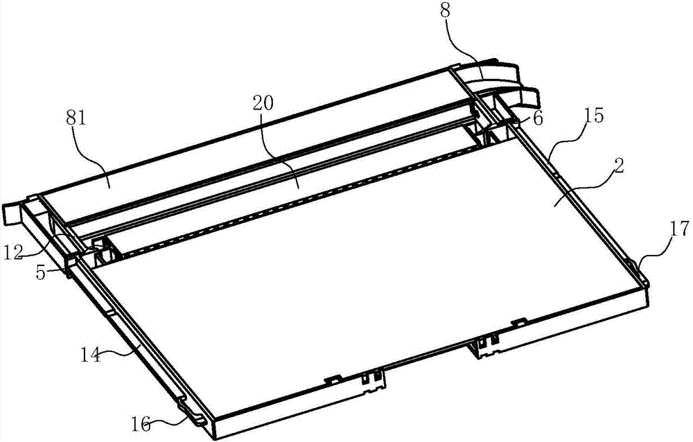
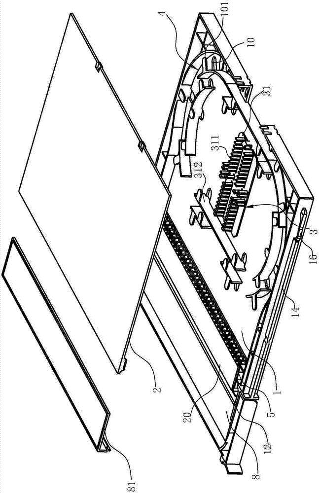
[0028] Such as Figure 1-11As shown, the high-density fusion splicing fiber distribution tray includes a base 1 and a cover plate 2. The side wall of the base 1 is surrounded to form a cavity 11. The cover plate 2 can cover the cavity 11. The base 1 and the cover plate 2 form a cavity 11. The accommodating space accommodates a fusion splice tray 3 and a wiring tray 4 at the same time. The central part of the base 1 is provided with a fusion splice tray 3. The center of the fusion splice tray 3 has a fusion splice seat 31 for welding optical fibers and pigtails, and the fusion splice seat 31 has 24 cores or 36-core card slot 311, and the fusion splice seat 31 has a wire slot 312 for cables to pass through, and the distribution board 4 is arranged on the outer periphery of the fusion splice tray 3 and formed with a fiber storage area. The fiber ...


PUM


Abstract

The invention relates to a high-density fusion welding and fiber adaptation tray comprising a pedestal and a cover plate. The side wall of the pedestal is surrounded so that a concave cavity is formed. The cover plate can cover the concave cavity. The high-density fusion welding and fiber adaptation tray is characterized in that a fusion welding disc and a wire distribution disc are accommodated in an accommodating space formed by the pedestal and the cover plate. The two sides of the opening of the front side wall of the pedestal are provided with a first installing base and a second installing base which are used for internal installation of a tail fiber adapter. The first and second installing bases are respectively provided with a positioning structure capable of positioning the adapter. Compared with trays in the prior art, advantages of the high-density fusion welding and fiber adaptation tray are that fusion welding disc and the wire distribution disc are simultaneously accommodated in the accommodating space formed by the pedestal and the cover plate so that space occupation is low, the layout mode of a conventional fusion welding and fiber adaptation tray is changed, and capacity can be effectively enlarged under the premise of maintaining arrangement dimension consistent with a telecom trunk tray. Meanwhile, the two sides of the front side wall of the pedestal are provided with the first installing base and the second installing base so that the adapter and the pedestal can be detachably connected to be flexibly adaptive to multiple tail fiber adapters, and thus the high-density fusion welding and fiber adaptation tray has the characteristic of high generality.

Description

technical field [0001] The present invention relates to an integrated module, in particular to a high-density fusion spliced ​​fiber distribution tray with a fusion splicing structure for left and right fibers, incoming cables, and a structure for absorbing redundant pigtails at the rear end of the tray. Background technique [0002] At present, the integrated optical fiber fusion module used in optical fiber communication technology in the market is mainly based on 12-core bundle pigtail fusion splicing and wiring. The production process of 12-core bundle pigtail is complicated, the cost is high, it is not easy to replace, and the construction and maintenance costs are high. For example, a Chinese utility model patent "Integrated Tray Structure for Distribution Cable Fusion Storage" with patent number ZL201220044133.5 (notification number CN 202453562 U) discloses such an integrated tray structure for distribution cable fusion storage, including a tray body, a tray body Inc...

Claims


Application Information

Patent Timeline
Patent Type & Authority Patents(China)
IPC IPC(8): G02B6/255
CPCG02B6/2556
Inventor 陈正龙
Owner 宁波隆兴电信设备制造有限公司
Why Eureka
Try Eureka