
A connection structure of laser reflector mounting seat

A lens mounting seat and connection structure technology, which is applied in the field of lasers, can solve the problems of inconvenient disassembly and maintenance, unreliable fixation, and easy rusting of screws, and achieve the effects of stable structure, fast and easy installation process, buffering and collision avoidance

Active Publication Date: 2018-05-08
JIANGSU ZHUOYUAN LASER TECH
View PDF7 Cites 0 Cited by
  • Summary
  • Abstract
  • Description
  • Claims
  • Application Information

AI Technical Summary

Problems solved by technology

[0002] At present, the laser emitting lens and reflecting lens are fixed by the lens mounting seat. Usually, there is a mounting groove on the lens mounting seat for fixing the lens. The lens mounting seat is generally fixed on the back seat by several screws. , but this method is cumbersome to install, inconvenient to disassemble and repair, small screws are easy to rust, and the fixation is not firm, etc., so the present invention provides a mounting structure for the mounting seat, which has novel structure, convenient installation, and firm structure

Method used


Image

  • A connection structure of laser reflector mounting seat
  • A connection structure of laser reflector mounting seat
  • A connection structure of laser reflector mounting seat

Examples


Embodiment Construction

[0020] The content of the present invention will be further described in detail below in conjunction with the accompanying drawings.

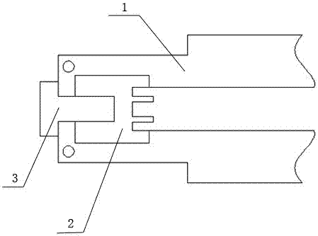
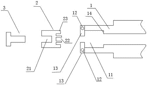
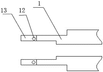
[0021] Such as figure 1 As shown, a connection structure of a laser reflector mounting seat includes a transmitting device 1 , a mounting seat 2 , and a connecting screw 3 . The interior of the emitting device 1 is used for installing electrode plates. Such as figure 2 As shown, one end of the launching device 1 is provided with a housing chamber 11 for housing the mounting base 2 , and a rotating member 13 is vertically provided at the upper and lower ends of the housing chamber 11 . Such as Figure 4 As shown, the two rotating parts 13 are arranged opposite to each other, and the opposite inner sides of the two rotating parts 13 are respectively provided with arc-shaped threaded areas 131 , and the relative outer sides are movably and rotatably connected to the upper and lower ends of the outer side of the accommodating cavity 11 . The u...


PUM


Abstract

The invention discloses a connection structure of a laser reflector mounting seat, which comprises a launching device, a mounting seat and a connecting screw; one end of the launching device is provided with an accommodation chamber; the upper and lower ends of the outer side of the accommodation chamber are vertically provided One rotating part; the two rotating parts are arranged opposite to each other, and the relative inner sides of the two rotating parts are respectively provided with arc-shaped threaded areas, and the relative outer sides are movable and rotatably connected to the upper and lower ends of the outer side of the accommodating cavity; the upper and lower two arcs The shaped threaded areas match each other to form an internal thread channel; one end of the mounting seat is provided with an internal thread hole, and the other end is provided with a mounting groove, and the mounting seat is installed in the receiving chamber at one end of the launching device; the connecting screw passes through the threaded The internal thread channel formed by the two arc-shaped threaded areas is sequentially connected with the internal thread hole at one end of the mounting seat. The installation process of the invention is quick and easy, and the structure is stable.

Description

technical field [0001] The invention relates to a laser, in particular to the installation structure of the laser reflector mounting seat. Background technique [0002] At present, the laser emitting lens and reflecting lens are fixed by the lens mounting seat. Usually, there is a mounting groove on the lens mounting seat for fixing the lens. The lens mounting seat is generally fixed on the back seat by several screws. , but such a method is cumbersome to install, inconvenient to disassemble and overhaul, small screws are prone to rust, and the fixation is not firm, etc., so the present invention provides a mounting structure for the mounting seat, which is novel in structure, convenient in installation, and firm in structure. Contents of the invention [0003] Aiming at the shortcomings of the above-mentioned prior art, the problem to be solved by the present invention is: to provide a connecting structure of a reflector mounting seat which is convenient for installation ...

Claims


Application Information

Patent Timeline
Patent Type & Authority Patents(China)
IPC IPC(8): H01S3/02
Inventor 万胜文
Owner JIANGSU ZHUOYUAN LASER TECH
Learn More