Mechanical connecting part

A connector and mechanical technology, which is applied in the direction of connecting components, shrinkage connections, mechanical equipment, etc., can solve problems such as connector falling off, and achieve the effect of overcoming the falling off

Inactive Publication Date: 2019-04-05
嘉兴市劼力机械科技有限公司
View PDF0 Cites 0 Cited by
  • Summary
  • Abstract
  • Description
  • Claims
  • Application Information

AI Technical Summary

Problems solved by technology

[0002] Most of the connectors in the prior art are socketed or threaded. The disadvantage is that the connectors are likely to fall off when they vibrate for a long time.

Method used


Image

  • Mechanical connecting part
  • Mechanical connecting part

Examples


Embodiment Construction

[0011] The present invention discloses a mechanical connector. The specific implementation manner of the present invention will be further described below in combination with preferred embodiments.

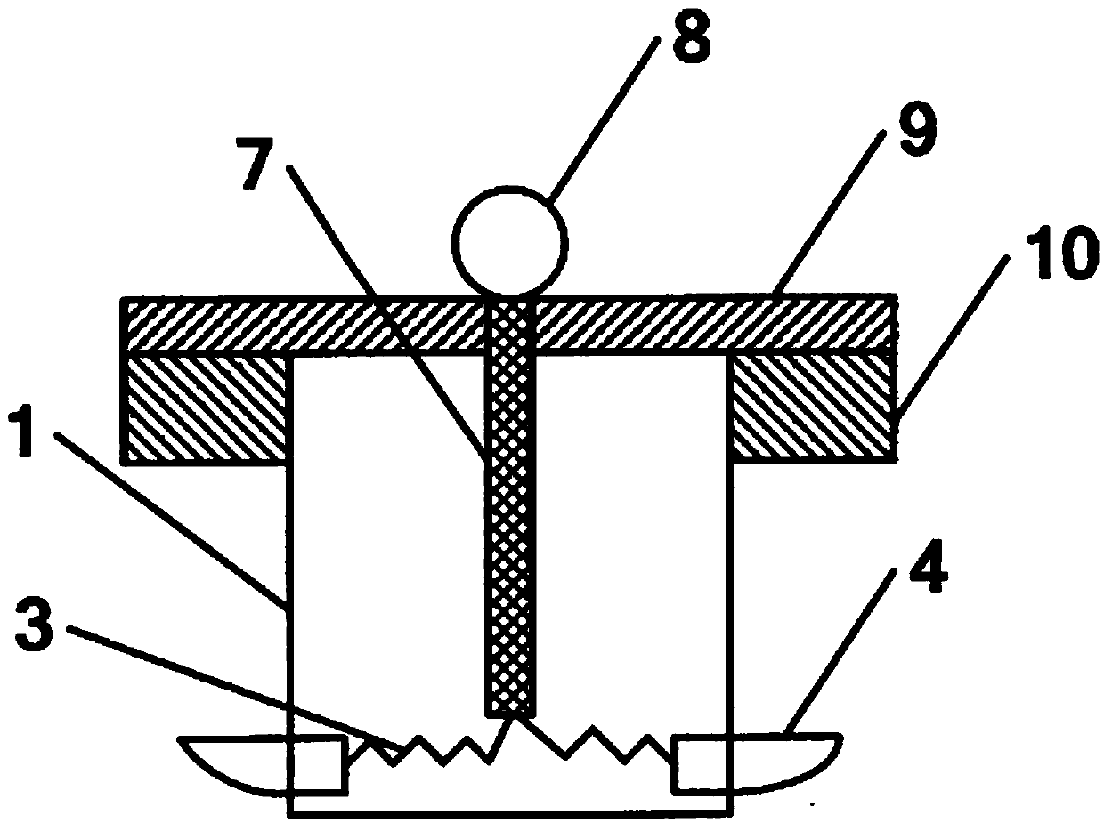
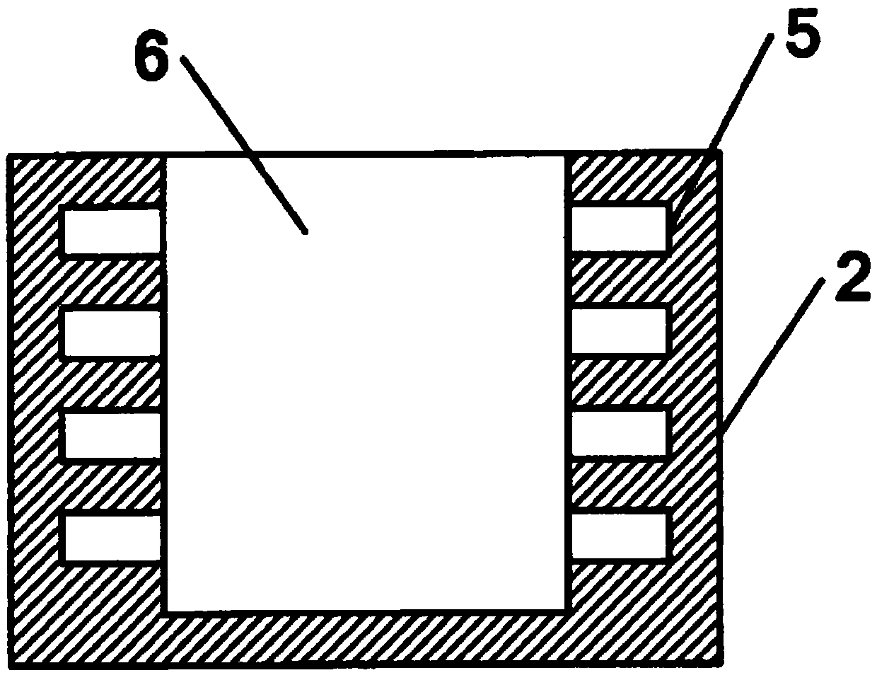
[0012] see attached figure 1 and figure 2 , figure 1 and figure 2 The structure of the present invention is shown. The mechanical connector includes a button cap 1 and a button body 2. The inside of the button cap 1 is set as a hollow structure and the bottom of the button cap 1 is provided with an opening. The opening There is a card and part 4 embedded in the place, the front end of the card and part 4 passes through the opening, and the rear end of the card and part 4 is located inside the buckle cap 1 and connected with the spring 3; the buckle body 2 is provided with the buckle cap 1. A cavity 6 with a suitable shape, with several snap rings 5 ​​extending outward on both sides of the cavity 6; the depth of the snap rings 5 ​​is consistent with the length of the front end...


PUM


Abstract

The invention discloses a mechanical connecting part and belongs to the technical field of connecting parts. The mechanical connecting part comprises a buckle cap and a buckle body. The interior of the buckle cap is of a hollow structure, and the bottom of the buckle cap is provided with an opening. Clamping parts are inlaid at the opening. The front ends of the clamping parts penetrate through the opening. The rear ends of the clamping parts are located in the buckle cap and connected with a spring. The buckle body is provided with a cavity matched with the buckle cap in shape. A plurality ofclamping rings extend outwards from the two sides of the cavity. The depth of the clamping rings is equal to the length of the front ends of the clamping parts. The mechanical connecting part provided by the invention is clamped into the clamping rings through the clamping parts to achieve the connection purpose, and the problem that the connecting part falls off is solved.

Description

technical field [0001] The invention belongs to the technical field of connectors, and in particular relates to a mechanical connector. Background technique [0002] Most of the connectors in the prior art are socketed or threaded. The disadvantage is that the connectors are likely to fall off when they vibrate for a long time. Contents of the invention [0003] The present invention provides a mechanical connector aiming at the state of the prior art. [0004] The present invention adopts the following technical solution, the mechanical connector includes a buckle cap and a buckle body, the inside of the buckle cap is set as a hollow structure and the bottom of the buckle cap is provided with an opening, and a card is embedded in the opening And part, the front end of the card and part passes through the opening, the rear end of the card and part is located inside the buckle cap and connected with the spring; the buckle body is provided with a cavity adapted to the shape...

Claims


Application Information

Patent Timeline
Patent Type & Authority Applications(China)
IPC IPC(8): F16B1/00F16B4/00
CPCF16B1/00F16B4/00
Inventor 陈国强
Owner 嘉兴市劼力机械科技有限公司
Why Eureka
Try Eureka