Charging method, a charger and a charging module

A charging method and charging module technology, which are applied in the charging/discharging of secondary batteries, current collectors, battery circuit devices, etc., can solve the problem of temperature rise of charging modules, and achieve the effect of reducing heat and ensuring charging efficiency.

Active Publication Date: 2015-11-25
LENOVO (BEIJING) CO LTD
View PDF6 Cites 8 Cited by
  • Summary
  • Abstract
  • Description
  • Claims
  • Application Information

AI Technical Summary

Problems solved by technology

[0006] In view of this, the present invention provides a charger, a charging module and a charging method, which solve the problem of severe temperature rise of the charging module during the existing fast charging

Method used


Image

  • Charging method, a charger and a charging module
  • Charging method, a charger and a charging module
  • Charging method, a charger and a charging module

Examples


Embodiment Construction

[0078] The following will clearly and completely describe the technical solutions in the embodiments of the present invention with reference to the accompanying drawings in the embodiments of the present invention. Obviously, the described embodiments are only some, not all, embodiments of the present invention. Based on the embodiments of the present invention, all other embodiments obtained by persons of ordinary skill in the art without making creative efforts belong to the protection scope of the present invention.

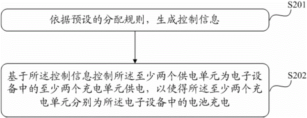
[0079] Please refer to the attached figure 2 , is a flow chart of Embodiment 1 of a charging method provided by the present invention, the method is applied to a charger having at least two power supply units, and at least two power supply units in the charger can be electronic devices connected to the charger Provides two supply currents.

[0080] Wherein, the charging method may include the following steps:

[0081] Step S201: Generate control information...


PUM


Abstract

The invention provides a charging method. At least two power supply units in a charger are controlled to supply electricity to at least two charging units in electronic equipment, so that the at least two charging units in the electronic equipment respectively charge batteries in the electronic equipment. By the method, the charger can provide at least two power supply current to the electronic equipment. Correspondingly, the electronic equipment also comprises a plurality of charging units; the plurality of charging units can respectively charge the batteries on the basis of at least two power supply current; each charging unit only needs to obtain relatively low power; various charging units can realize charging of the batteries with relatively high power as a whole; in the rapid charging process, various charging units only need to provide relatively low power under the premise of ensuring the charging efficiency; and relatively low heat is generated, so that a charging module does not generate a violent temperature rise.

Description

technical field [0001] The invention relates to the field of electronic equipment, and more specifically relates to a charging method, a charger and a charging module. Background technique [0002] With the development of electronic technology, the demand for fast charging is becoming stronger and stronger in the daily use of electronic equipment, and various fast charging technologies emerge in an endless stream. The essence of this fast charging is to convert the current provided by the external charger into a larger current. Charge the battery. [0003] Such as figure 1 Shown is a schematic diagram of fast charging in the prior art, the charger 101 provides 12V / 2A charging power for the mobile terminal 102, and the charging IC (integrated circuit, integrated circuit) 103 in the mobile terminal performs power conversion, and converts it into the battery charging required The charging current is 4.35V / 4A, and the charging current is output to the battery 104 to complete t...

Claims


Application Information

Patent Timeline
Patent Type & Authority Applications(China)
IPC IPC(8): H02J7/00H02J7/02H01M10/44G01K7/00
CPCY02B40/00Y02E60/10
Inventor 廖火生
Owner LENOVO (BEIJING) CO LTD
Why Eureka
Try Eureka