Dynamic resource allocation method and device, base station, terminal

An allocation method and dynamic resource technology, applied in the field of communication, can solve the problems of LTE control channel scheduling high-frequency carrier, high control signaling overhead, etc.

Active Publication Date: 2019-05-07
ZTE CORP
View PDF4 Cites 0 Cited by
  • Summary
  • Abstract
  • Description
  • Claims
  • Application Information

AI Technical Summary

Problems solved by technology

[0012] Aiming at the problems in the related technologies that the LTE control channel cannot be used to schedule the uplink and downlink services and uplink service transmissions of multiple transmission symbols on the high-frequency carrier, and in the independent networking network of the LTE carrier and the high-frequency carrier, the control signaling overhead is relatively large, etc., this paper The invention provides a dynamic resource allocation method and device, a base station, and a terminal to at least solve the above technical problems

Method used


Image

  • Dynamic resource allocation method and device, base station, terminal
  • Dynamic resource allocation method and device, base station, terminal
  • Dynamic resource allocation method and device, base station, terminal

Examples


Embodiment 1

[0197] Assuming that there are at least two carrier elements linked to a terminal UE1, the two carrier elements can be located at the same node TP0 or at two different nodes TP1 and TP2, and TP1 and TP2 have ideal backhaul links (smaller backhaul delay). It is assumed that the LTE R12 carrier element is CC0, and the high-frequency carrier element is CC1. When the base station wants to send downlink data to UE1 on CC1 and expects UE1 to receive it correctly, the base station sends corresponding downlink control indication signaling on CC0 to indicate the time domain resource position of the downlink data corresponding to UE1 on CC1. Such as Figure 5 shown. Wherein, it is assumed that CC0 is a 4G LTE carrier, and CC1 is a high-frequency carrier. DR means that UE1 receives downlink data on CC1. HARQ means that UE1 feeds back the HARQ information for downlink data on the uplink carrier corresponding to CC0. RR means that UE1 receives and retransmits downlink data on the high-fr...

Embodiment 2

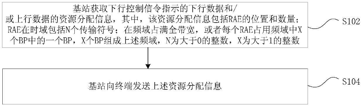
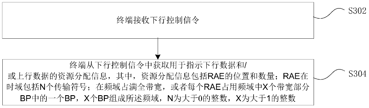
[0214] The base station indicates the number of corresponding downlink data resource allocation time units by using the downlink control indication signaling in a predetermined manner. The RAE is composed of N (N>0) transmission symbols in the time domain, and the N value base station and the terminal can be defined in a predefined manner, wherein there is a one-to-one correspondence between the N value and the 4G LTE carrier element bandwidth, or There is a corresponding relationship between the N value and the bandwidth of the high-frequency carrier element, as shown in Table 2. Wherein Zn (1-4) is an integer greater than zero.

[0215] Table 2

[0216] System Bandwidth (MHz)

N value selection

≤X1

Z1

X1+1~X2

Z2

X2+1~X3

Z3

X3+1~X4

Z4

[0217] The base station schedules UE1 to receive downlink data on one or more corresponding RAEs on the downlink carrier corresponding to CC1 through the DL Grant signaling on the downl...

Embodiment 3

[0231] The base station indicates the number of corresponding downlink data resource allocation time units by using the downlink control indication signaling in a predetermined manner. The RAE is composed of N (N>0) transmission symbols in the time domain, and the N-value base station can be configured to the terminal through high-layer signaling. Preferably, the predefined N value is one of the following values: 24, 28, 30, 32, 40, 42.

[0232] The base station schedules UE1 to receive downlink data on one or more corresponding RAEs on CC1 through DL Grant signaling on the 4G carrier CC0.

[0233] When the maximum time window scheduled by DL Grant is when, and includes Y RAEs, then the base station instructs UE1 to receive downlink data in one or more RAEs of the Y RAEs. Preferably, the value of Y is 10, or the value of Y is the number of RAEs included in the time domain within 1 ms.

[0234]Preferably, when the first resource allocation mode is adopted in the DL Grant ...


PUM


Abstract

The present invention provides a dynamic resource allocation method and device, a base station, and a terminal, wherein the method includes: the base station acquires resource allocation information of downlink data and / or uplink data indicated by downlink control signaling, wherein the resource allocation information includes The location and number of resource allocation units RAE; RAE includes N transmission symbols in the time domain; occupies the full bandwidth in the frequency domain, or each RAE occupies one BP in the X bandwidth part BP in the frequency domain, and X BPs form a frequency domain, N is an integer greater than 0, and X is an integer greater than 1; the base station sends resource allocation information to the terminal, adopts the above-mentioned technical solution provided by the present invention, and solves the problem that the LTE control channel cannot be used to schedule multiple high-frequency carriers in related technologies. Transmission of symbols for uplink and downlink business and uplink business transmission, and in the independent networking network of LTE carrier and high-frequency carrier, control signaling overhead and other issues, so as to realize LTE carrier cross-carrier scheduling of high-frequency carrier.

Description

technical field [0001] The present invention relates to the communication field, in particular to a method and device for allocating dynamic resources, a base station, and a terminal. Background technique [0002] In high-frequency communication, since a higher carrier frequency is used for transmission, the average path loss will be much larger than that of the traditional Long-Term Evolution (LTE) system. For example, we use a carrier frequency of 28GHz for transfer, using the formula: [0003] L f Indicates the path loss of the LTE system; the calculated average ratio information between the high-frequency path loss value and the LTE path loss value is: [0004] L H Indicates the path loss of high-frequency communication; [0005] In order to ensure coverage in high-frequency communication, that is, the receiving side meets the minimum SINR requirement, it is necessary to increase the gain of the transmitter and receiver. [0006] [0007] Among them, P r Ind...

Claims


Application Information

Patent Timeline
Patent Type & Authority Patents(China)
IPC IPC(8): H04L5/00H04W72/12
CPCH04L5/001H04L5/0044H04L5/0082H04L5/0091H04L5/0055H04W72/21H04W72/23H04W72/0453H04W72/12
Inventor 李春旭郭森宝张峻峰
Owner ZTE CORP
Why Eureka
Try Eureka