Synchronous reluctance motor and rotor for synchronous reluctance motor
一种同步磁阻、电动机的技术,应用在用于单相电流的同步电动机、同步机、电动组件等方向,能够解决功率损耗、弱磁场控制、永磁体机械强度、耐热性问题等问题,达到提高转矩和功率因数的效果
- Summary
- Abstract
- Description
- Claims
- Application Information
AI Technical Summary
Problems solved by technology
Method used
Image

Examples
no. 1 approach
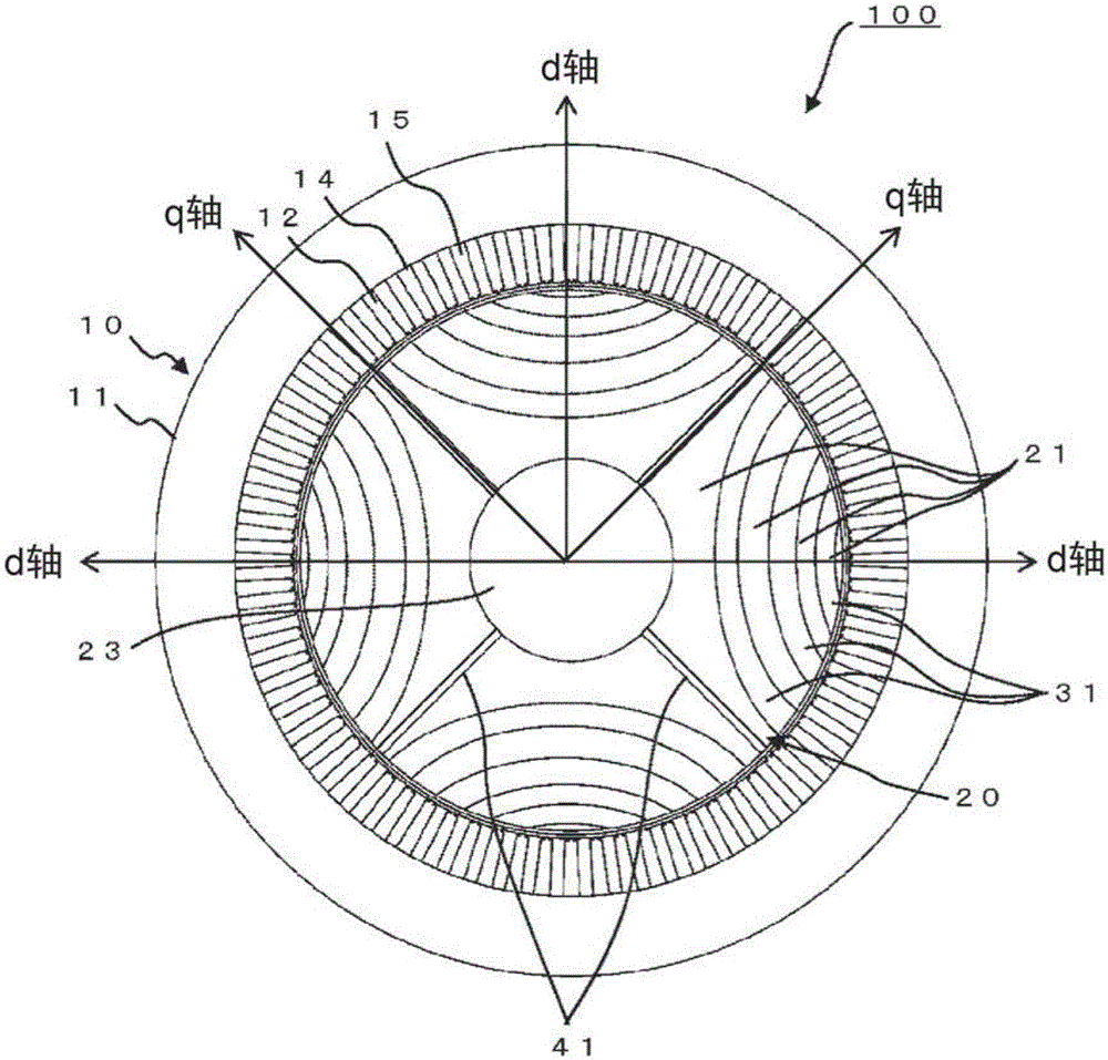
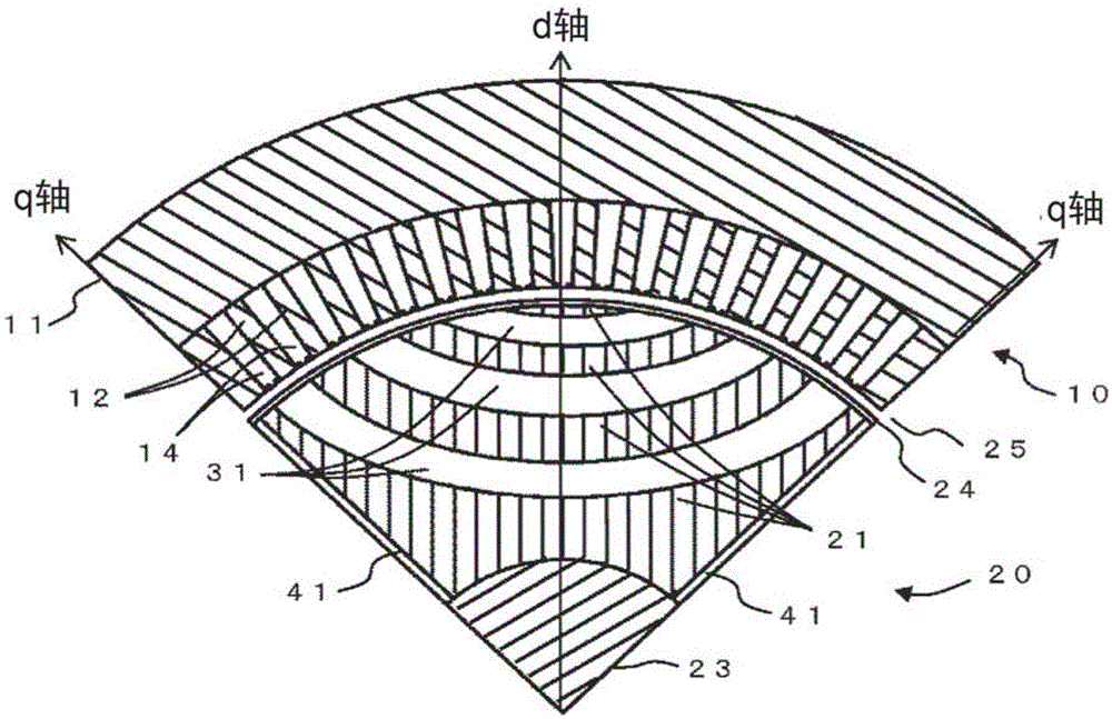
[0033] figure 1 It is a cross-sectional view perpendicular to the rotation axis direction of the synchronous reluctance motor according to the first embodiment. In addition, figure 2 It is a partial cross-sectional view showing a detailed cross section perpendicular to the rotation axis direction of the synchronous reluctance motor according to the first embodiment. figure 2 The middle is 1 / 4 of the cross section. Although only 1 / 4 of the figure is shown for convenience of explanation, it does not mean that the synchronous reluctance motor can be divided into four.
[0034] The synchronous reluctance motor 100 has a stator 10 and a rotor 20 inside a housing (not shown).
[0035] The stator 10 has a stator core 11 and a plurality of stator teeth 12.
[0036] The stator core 11 has a structure in which electromagnetic steel sheets are laminated in the rotation direction, and the electromagnetic steel sheets are thin plates made by adding silicon to iron in order to reduce eddy curren...
no. 2 approach
[0074] Figure 8 It is a cross-sectional view perpendicular to the rotation axis direction of the synchronous reluctance motor according to the second embodiment. This embodiment is a modification of the first embodiment.
[0075] The star shaft 50 has four radial plates 51 each extending outward in the radial direction. The four radial plates 51 are arranged at intervals in the circumferential direction and extend along the rotation axis direction of the rotor 20. Here, although the case where there are four radial plates 51 is shown, it is not limited to four. The multiple pieces may be, for example, 6 pieces or the like.
[0076] The radial plate 51 in the second embodiment is arranged in the area where the q-axis direction magnetic flux barrier 41 is formed in the first embodiment. The material of the star shaft 50 is a non-magnetic body. Therefore, similar to the q-axis direction magnetic flux barrier 41 in the first embodiment, the magnetic resistance is large and the magn...
no. 3 approach
[0083] Picture 9 It is a partial cross-sectional view of a detailed cross section perpendicular to the rotation axis direction of the synchronous reluctance motor according to the third embodiment. This embodiment is a modification of the first embodiment.
[0084] In the first embodiment, the d-axis surrounding magnetic flux barrier 31 and the q-axis direction magnetic flux barrier 41 are air layers, but in the third embodiment, the d-axis surrounding magnetic flux barrier 32 and the q-axis direction magnetic flux barrier 42 are Filled with non-magnetic resin.
[0085] In the present embodiment thus constituted, since the d-axis surrounding magnetic flux barrier 32 and the q-axis direction magnetic flux barrier 42 are made of non-magnetic resin, the magnetic flux barrier can be formed as in the first embodiment.
[0086] Therefore, since the q-axis direction magnetic flux barrier 42 plays the same role as the q-axis magnetic flux barrier 41 in the first embodiment, the salient pol...
PUM
 Abstract
Description
Claims
Application Information
 - R&D
- Intellectual Property
- Life Sciences
- Materials
- Tech Scout
- Unparalleled Data Quality
- Higher Quality Content
- 60% Fewer Hallucinations
Browse by: Latest US Patents, China's latest patents, Technical Efficacy Thesaurus, Application Domain, Technology Topic, Popular Technical Reports.
© 2025 PatSnap. All rights reserved.Legal|Privacy policy|Modern Slavery Act Transparency Statement|Sitemap|About US| Contact US: help@patsnap.com