
Stator and rotor structure of high-power-density reluctance motor

A high power density, reluctance motor technology, applied in the direction of magnetic circuit shape/style/structure, magnetic circuit rotating parts, magnetic circuit, etc., to improve salient pole ratio, uniform stator magnetic density distribution, and reduce torque fluctuation Effect

Active Publication Date: 2020-03-27
HANGZHOU EASITECH
View PDF6 Cites 0 Cited by
  • Summary
  • Abstract
  • Description
  • Claims
  • Application Information

AI Technical Summary

Problems solved by technology

At present, there is no relevant technical article to analyze the coupling design of the synchronous reluctance motor stator / rotor related structure dimensions

Method used


Image

  • Stator and rotor structure of high-power-density reluctance motor
  • Stator and rotor structure of high-power-density reluctance motor
  • Stator and rotor structure of high-power-density reluctance motor

Examples


Embodiment Construction

[0040] The present invention will be further described below in conjunction with specific examples, but the present invention is not limited to these specific implementations. Those skilled in the art will realize that the present invention covers all alternatives, modifications and equivalents as may be included within the scope of the claims.

[0041] In describing the present invention, it should be understood that the terms "center", "longitudinal", "transverse", "length", "width", "thickness", "upper", "lower", "front", " The orientations or positional relationships indicated by "rear", "left", "right", "vertical", "horizontal", "top", "bottom", "inner", "clockwise", "counterclockwise" are based on the attached The orientation or positional relationship shown in the figure is only for the convenience of describing the present invention and simplifying the description, and does not indicate or imply that the referred device or element must have a specific orientation, be c...


PUM


Abstract

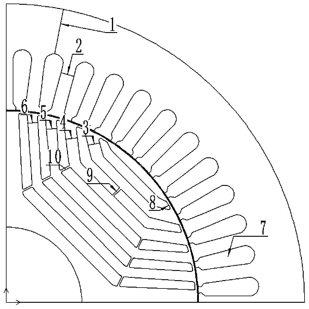
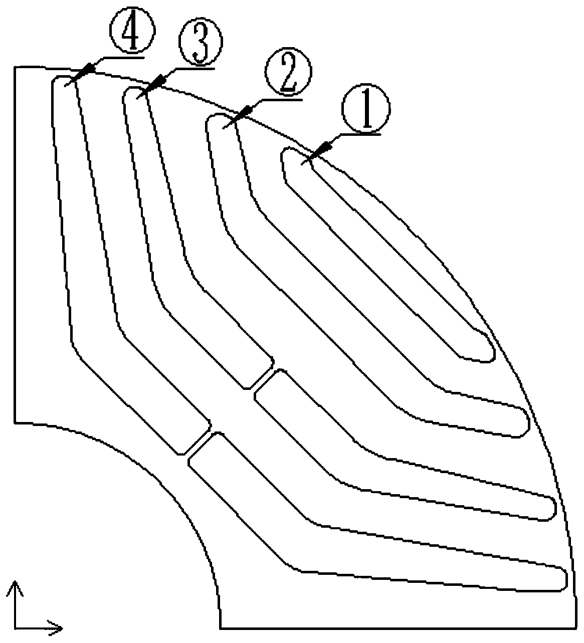
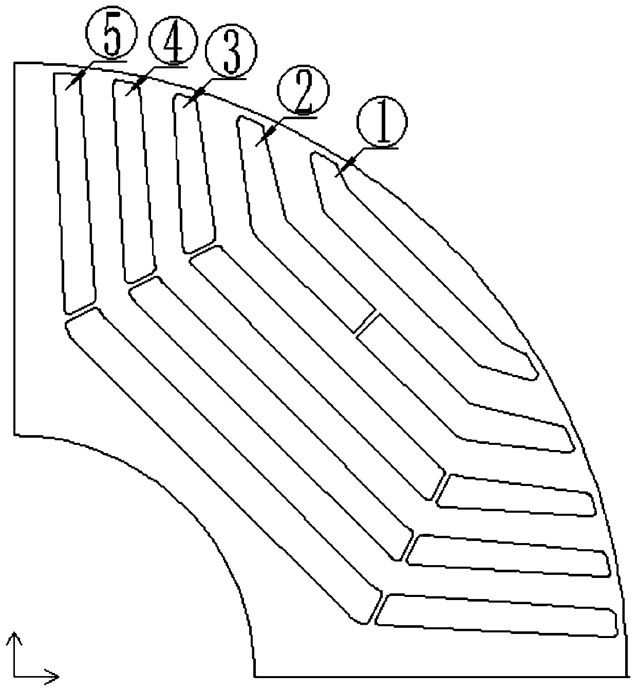
The invention discloses a stator and rotor structure of a high-power-density reluctance motor. The structure comprises a stator and a rotor, the number of stator slots and the number of rotor magneticbridges meet the formula (1): Nr = Ns-4k (1), Ns is the number of stator slots corresponding to each pair of poles, Nr is the number of rotor magnetic bridges corresponding to each pair of poles, K is a positive integer, and the number of rotor magnetic bridges corresponding to each layer of rotor magnetic barriers is 2; the number of layers of the rotor magnetic barriers is Nr / 2, and then rounding is carried out; the opening angle alpha of the outermost layer magnetic bridge of the rotor meets the formula (2), wherein p is the number of pole pairs. According to the invention, the leakage flux of the motor can be reduced, the salient pole ratio of the motor is improved, the torque output capability of the motor is improved, and the torque ripple of the motor can be reduced.

Description

technical field [0001] The invention belongs to the technical field of motors, and in particular relates to a stator-rotor structure of a high-power-density reluctance motor. Background technique [0002] Compared with the asynchronous motor, the synchronous reluctance motor has no winding on the rotor, no rotor copper loss, and basically no rotor heating problem, which improves the operating efficiency and safety of the motor. Compared with the permanent magnet synchronous motor, there is no permanent magnet on the rotor, which greatly reduces the cost of the motor under the condition of the same power. At the same time, the speed range is wide, and there is no problem of high temperature loss of magnetism. In summary, the application market potential of synchronous reluctance motors to replace asynchronous motors and permanent magnet motors is huge. [0003] The influence of the stator structure on the magnetic circuit mainly includes the size of the stator teeth and the ...

Claims


Application Information

Patent Timeline
IPC IPC(8): H02K1/16H02K1/22
CPCH02K1/165H02K1/22H02K2213/03
Inventor 王明轩方卫中晋兆海
Owner HANGZHOU EASITECH
Learn More