Rotor slotless switched reluctance motor

A switched reluctance motor without cogging technology, which is applied to electrical components, electromechanical devices, magnetic circuit static parts, etc., can solve the problems of non-constant synthetic torque, non-linear current, large torque ripple, etc., and achieve Effects of reduced volume and torque ripple, reduced volume, and shortened magnetic circuit length

Inactive Publication Date: 2013-06-05
DALIAN UNIV OF TECH
View PDF5 Cites 0 Cited by
  • Summary
  • Abstract
  • Description
  • Claims
  • Application Information

AI Technical Summary

Problems solved by technology

Switched reluctance motors can be designed into single-phase, two-phase, three-phase and multi-phase different structures, and have single-tooth per pole and multi-tooth per pole structures. The double salient pole structure and switching power supply of traditional switched reluctance motors lead to its It has certain disadvantages: first, the marginal flux generated before the stator teeth and rotor teeth overlap causes current nonlinearity; second, the torque on the rotor of the switched reluctance motor is superimposed by a series of pulse torques. moments are not constant
These will lead to the inherent torque ripple of the switched reluctance motor, especially when the motor is running at low speed, the torque ripple is large

Method used


Image

  • Rotor slotless switched reluctance motor
  • Rotor slotless switched reluctance motor
  • Rotor slotless switched reluctance motor

Examples


Embodiment Construction

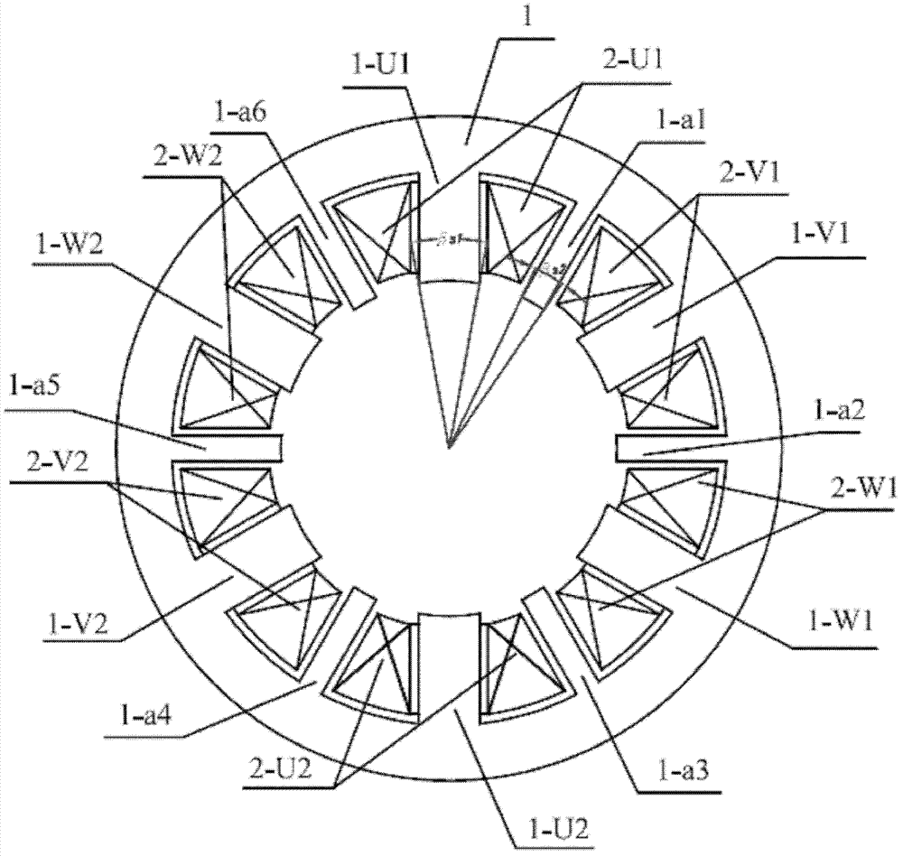
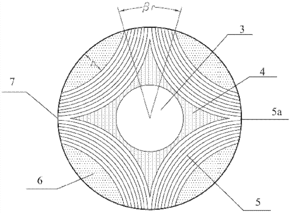
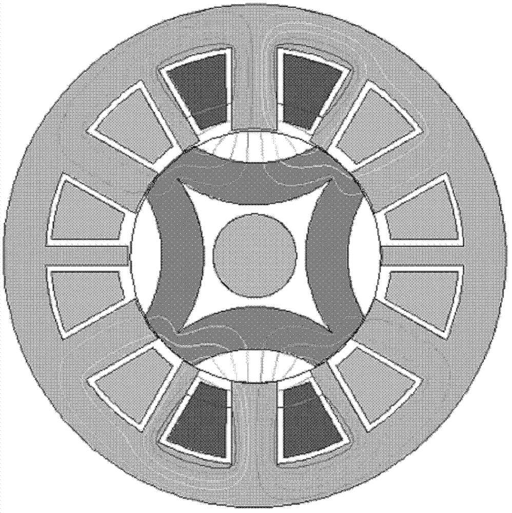
[0020] The specific implementation of the present invention will be described in detail below in conjunction with the accompanying drawings and technical solutions. The stator of the rotorless cogging switched reluctance motor adopts a combined magnetic pole structure, and the rotor adopts an anisotropic axial lamination structure. Considering the manufacturability of the axial lamination, the rotor is stacked into a 4-pole structure. According to the constraint relationship of the stator and rotor poles of the switched reluctance motor, the main poles of the stator are selected as 6 poles, and the number of auxiliary poles of the stator is determined accordingly, which is also 6 poles, so the poles of the stator and rotor are 12 / 4 poles. According to the relationship between the number of poles and the number of phases, the motor has 3 phases. The invented 3-phase 12 / 4-pole rotor slotless switched reluctance motor consists of a stator and a rotor, and the stator includes two ...


PUM


Abstract

The invention belongs to the field of electromechanical switched reluctance motors and relates to a rotor slotless switched reluctance motor, in particular to a switched reluctance motor having a rotor slotless structure. A stator of the rotor slotless switched reluctance motor has a magnetic pole structure which is formed by combining six main magnetic poles and auxiliary magnetic poles; a rotorhas an anisotropic axial lamination structure and is laminated into a four-pole structure; the axial lamination structure comprises a rotary shaft, a non-magnetic-conduction bracket, an axial lamination, a non-magnetic-conduction filling material and a non-magnetic-conduction fastening ring; and magnetic poles of the axial lamination are formed by alternately laminating a high-magnetic-conductionmaterial silicon steel sheet and a non-magnetic-conduction insulating material lamination along the axial direction. The rotor slotless switched reluctance motor has the advantages that: by adopting combined stator magnetic poles and an axial laminated rotor, the length of a magnetic path is reduced, the iron loss of the switched reluctance motor can be reduced, and the torque pulsation of the switched reluctance motor is effectively reduced; and windings are wound on the main magnetic poles, so that the windings are convenient to embed, the problem about insulation is solved, and the utilization rate of a slot is high.

Description

technical field [0001] The invention belongs to the field of electromechanical switched reluctance motors, and in particular relates to a rotor-free switched reluctance motor composed of a combined magnetic pole stator and an axially laminated rotor. Background technique [0002] The switched reluctance motor transmission system is a mechatronic AC speed control system, which has many advantages such as simple structure, reliable operation, flexible system control, good speed control performance, and high operating efficiency. It is especially suitable for harsh environments and ultra-high speed applications. Therefore, it is widely used in coal mines, aviation, automobiles and other fields. The power range is from several watts to several megawatts, and the speed range is from several to tens of thousands of revolutions. The traditional switched reluctance motor has a double-salient pole structure. There is neither winding nor permanent magnet on the rotor. Concentrated win...

Claims


Application Information

Patent Timeline
Patent Type & Authority Patents(China)
IPC IPC(8): H02K29/00H02K1/14H02K1/24H02K3/28
Inventor 孙建忠白凤仙孙斐然何月飞罗亚琴
Owner DALIAN UNIV OF TECH
Why Eureka
Try Eureka