Multi-combination type permanent magnet motor rotor punching sheet and permanent magnet motor

A technology for rotor punching and permanent magnet motors, which is applied in the direction of magnetic circuit rotating parts, magnetic circuits, electrical components, etc., can solve the problems of increasing material control, purchasing cost and process complexity, failing to meet performance requirements and noise standards, shock Problems such as chip R&D and production cycle lengthening, to achieve the effect of increasing output torque, reducing moment of inertia, and strong versatility

Active Publication Date: 2021-10-19
河南通宇新源动力有限公司
View PDF6 Cites 0 Cited by
  • Summary
  • Abstract
  • Description
  • Claims
  • Application Information

AI Technical Summary

Problems solved by technology

[0003] The general rotor punching is specially designed according to the performance of the motor, which cannot meet different performance requirements and noise standards.
The versatility of the existing rotor laminations is insufficient and cannot be applied to different performance requirements at the same time, which lengthens the R&D and production cycle of the laminations, and also increases material control, procurement costs and process complexity

Method used


Image

  • Multi-combination type permanent magnet motor rotor punching sheet and permanent magnet motor
  • Multi-combination type permanent magnet motor rotor punching sheet and permanent magnet motor
  • Multi-combination type permanent magnet motor rotor punching sheet and permanent magnet motor

Examples


Embodiment Construction

[0028] The present invention will be further described below in conjunction with accompanying drawing.

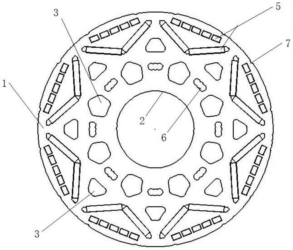
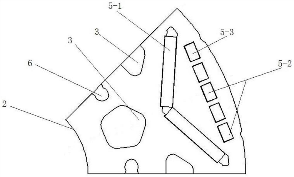
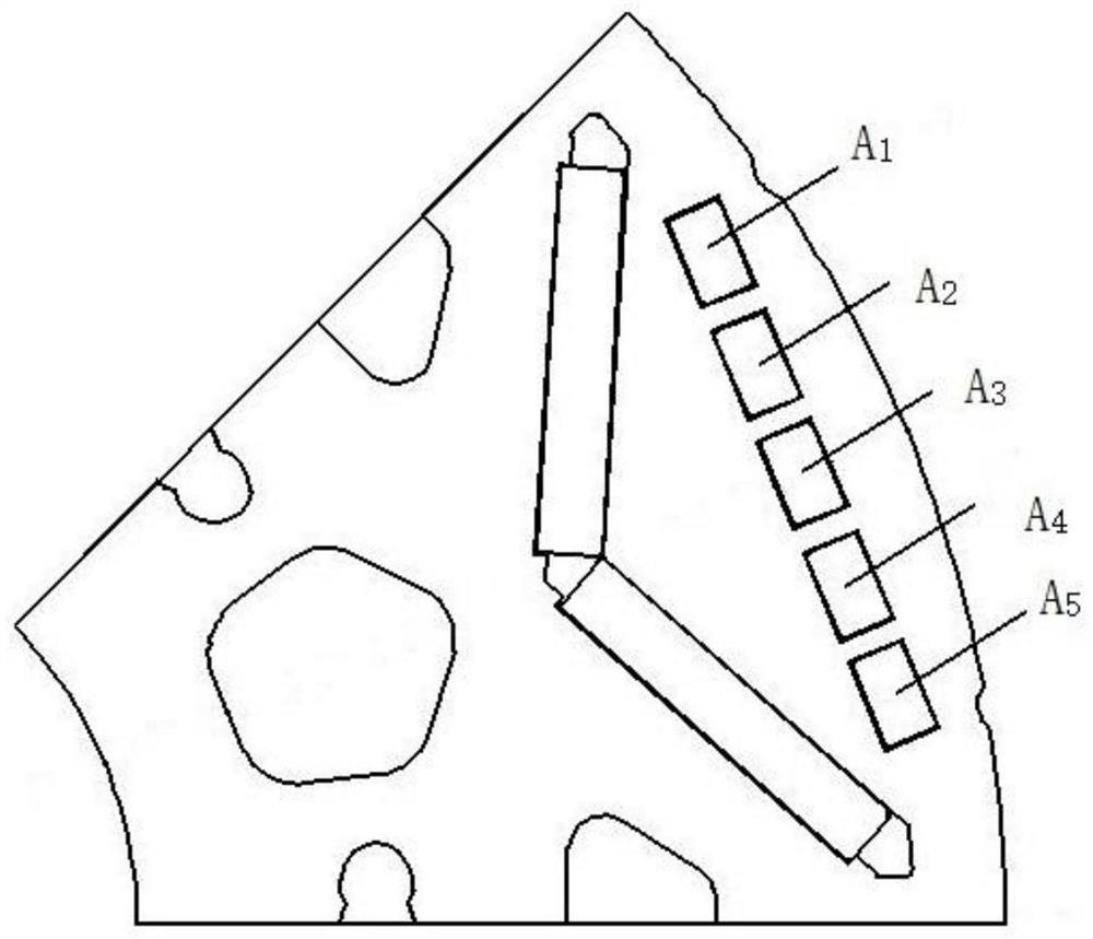
[0029] The present invention provides a multi-combinable permanent magnet motor rotor stamping, some of which are as follows Figure 1-3 As shown, it includes a circular rotor punching body 1, which is divided into a plurality of rotor poles 4 distributed in a circumferential array; the rotor punching body is provided with a shaft hole 2, a weight reduction hole 3 and a circumferential The inverted triangular magnetic steel slot 5 arranged circumferentially. The shaft hole is placed in the middle of the rotor punching body; the weight-reducing holes adopt one or more shapes of holes evenly distributed in the circumferential direction of the rotor punching body to reduce the moment of inertia of the motor and the weight of the whole machine. A set of inverted triangular magnetic steel grooves are arranged on a single rotor pole, and the inverted triangular magnetic steel gr...


PUM


Abstract

The invention discloses a multi-combination permanent magnet motor rotor punching sheet, which comprises a rotor punching sheet body. The rotor punching sheet body is divided into a plurality of rotor poles which are distributed in a circumferential array, the rotor punching sheet body is provided with a shaft hole, lightening holes and inverted triangular magnetic steel grooves which are distributed in the circumferential direction, and each rotor pole is matched with one inverted triangular magnetic steel groove. Each inverted triangular magnetic steel groove comprises linear magnetic steel grooves and two bevel magnetic steel grooves; the linear magnetic steel grooves are formed by arranging an odd number of rectangular magnetic steel grooves with the length of a and the width of b at intervals, and the number of the linear magnetic steel groove is n; and the length of each bevel magnetic steel groove is n * a, and the width of each bevel magnetic steel groove is b. According to the invention, permanent magnets are inserted into the appropriate magnetic steel grooves and matched with different small round holes to form corresponding skewed pole angles, so that different performance requirements of a motor are met, the research, development and production periods of the punching sheet are shortened, and the material management and control, the purchase cost and the process complexity are also reduced; and meanwhile, asymmetry of magnetic poles can be realized, so that the effects of weakening harmonic waves and reducing torque fluctuation are achieved.

Description

technical field [0001] The invention relates to the technical field of drive motors, in particular to a multi-combinable permanent magnet motor rotor punch and a permanent magnet motor. Background technique [0002] In the prior art, the asymmetrical magnetic poles are generally realized by shifting the magnetic poles by a certain angle or opening asymmetrical small holes on the rotor, and the skewed poles of the rotor are realized by stacking the same punching pieces forward and backward. For example, in the article "Electric MotorDesign of General Motors'Chevrolet Bolt Electric Vehicle", the rotor of the bolt motor is stamped to achieve rotor pole asymmetry through unequal magnetic pole angles and asymmetric holes; A single mold realizes the keyway scheme in the "rotor punching sheet with segmented and staggered poles" of the rotor to achieve positive and negative stacking. [0003] General rotor laminations are specially designed according to the performance of the motor...

Claims


Application Information

Patent Timeline
Patent Type & Authority Applications(China)
IPC IPC(8): H02K1/27
CPCH02K1/276H02K1/2766H02K2201/06H02K2201/15H02K2213/03Y02T10/64
Inventor 梁德志喻泽文钟运平杨国威陈兆辉李栋刘洋张梓梁
Owner 河南通宇新源动力有限公司
Why Eureka
Try Eureka