Permanent magnet synchronous motor and rotor thereof

A permanent magnet synchronous motor and rotor technology, applied to synchronous motors with stationary armatures and rotating magnets, motors, magnetic circuit rotating parts, etc., can solve problems such as poor sinusoidality, motor torque fluctuations, and large noise. Achieve the effects of reducing ripple, improving sine, and suppressing harmonic components

Pending Publication Date: 2022-07-12
成都华川电装有限责任公司
View PDF0 Cites 0 Cited by
  • Summary
  • Abstract
  • Description
  • Claims
  • Application Information

AI Technical Summary

Problems solved by technology

[0004] And because the permanent magnet synchronous motor is aimed at the common pole slot matching of 48 slots and 8 poles, when the rotor of the existing permanent magnet motor rotates along the circumferential direction, a large air gap harmonic magnetic field will be generated, the sinusoidality of the back EMF is poor, and the torque ripple is large And stator cogging effect, etc. lead to motor torque fluctuations and large noise

Method used


Image

  • Permanent magnet synchronous motor and rotor thereof
  • Permanent magnet synchronous motor and rotor thereof
  • Permanent magnet synchronous motor and rotor thereof

Examples


Embodiment Construction

[0038] The present invention will be described in further detail below with reference to the accompanying drawings and specific embodiments.

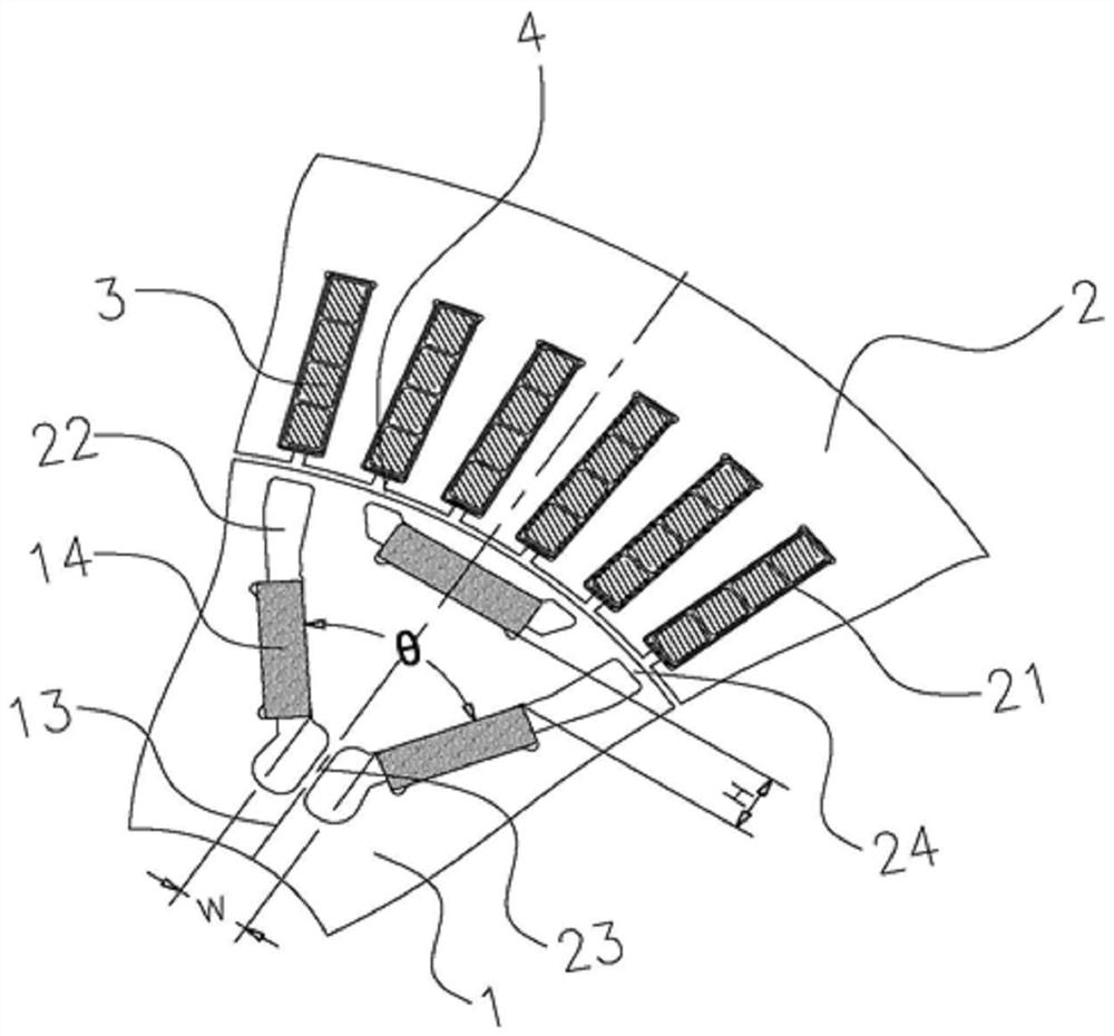
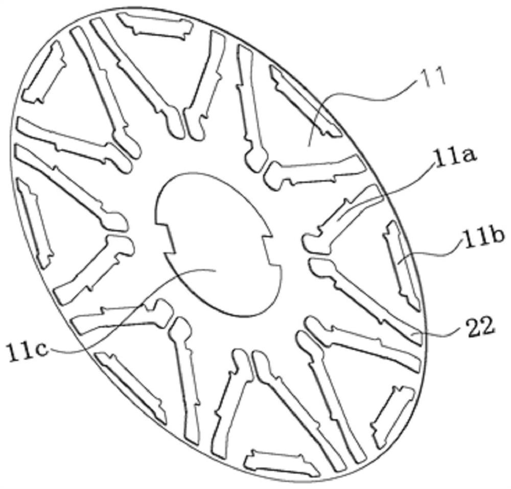
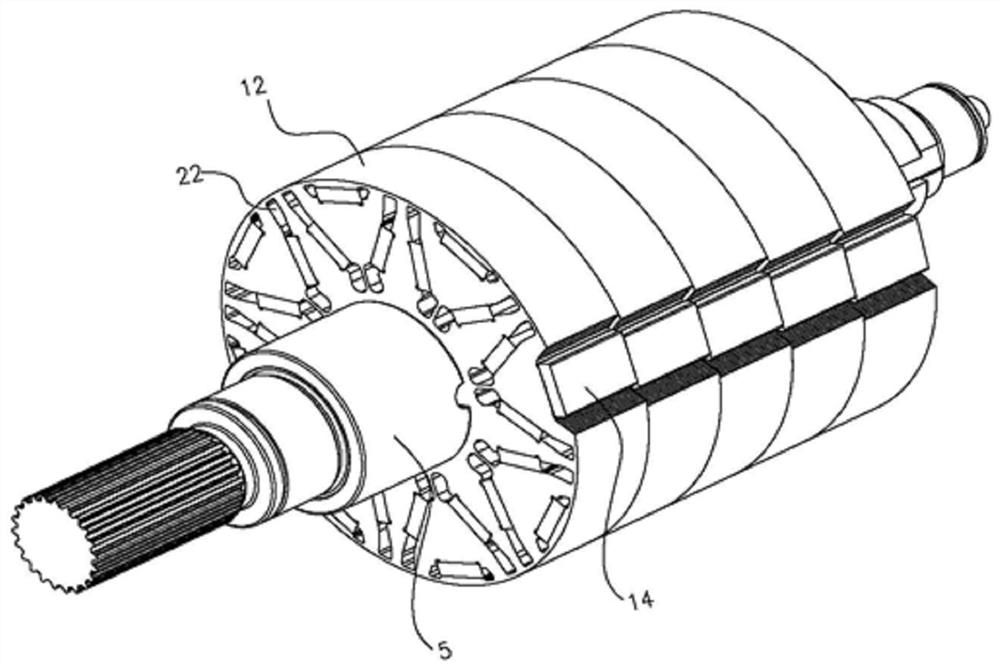
[0039] like Figure 1 to Figure 3 As shown, the rotor 1 of the permanent magnet synchronous motor of the present invention includes one or more iron core segments 12, each iron core segment 12 includes several rotor iron core pieces 11 and a plurality of magnetic pole groups, and each iron core segment 12 has a thickness of 0.2-0.5mm. The rotor iron core piece 11 is riveted and pressed, and the material of the rotor iron core piece 11 is preferably a silicon steel sheet.

[0040] The center of the rotor iron core 11 is provided with a mounting hole 11c connected to the main shaft 5, and the axial end surface of the rotor iron core 11 is provided with a plurality of sets of magnetic pole slots, each set of magnetic pole slots is equipped with a magnetic pole set, and each set of magnetic pole slots runs along the rotor. The radial direc...


PUM


Abstract

The invention discloses a rotor of a permanent magnet synchronous motor. Each group of magnetic pole slots is divided into two inner magnetic pole slots positioned on the inner layer and one outer magnetic pole slot positioned on the outer layer along the radial direction of a rotor iron core sheet; two of the magnetic pole groups are first permanent magnets, the other one of the magnetic pole groups is a second permanent magnet, after the first permanent magnets are matched with the inner magnetic pole grooves, the two first permanent magnets are arranged in a V shape, and a magnetic pole straight shaft which is axially symmetric about the two first permanent magnets is arranged between the two first permanent magnets; at least one end of the inner magnetic pole groove extends to form a magnetic isolation groove located on the outer side of the first permanent magnet. After the second permanent magnets are matched with the outer magnetic pole grooves, the symmetry axes of the second permanent magnets coincide with the magnetic pole straight axes, and the distance between the second permanent magnets and the peripheral face of the rotor iron core piece is smaller than the distance between the first permanent magnets and the peripheral face of the rotor iron core piece. According to the invention, the counter electromotive force can be reduced, the no-load counter electromotive force waveform sinusoidal property is improved, the reluctance torque is improved, and the cogging torque is reduced.

Description

technical field [0001] The invention relates to the field of permanent magnet synchronous motors, in particular to a permanent magnet synchronous motor and a rotor thereof. Background technique [0002] In recent years, permanent magnet synchronous motors have been widely used in various fields due to their high torque and power density, small size, light weight, high efficiency, and low rotor electromechanical time constant. [0003] Because the permanent magnet synchronous motor needs a matching controller to work properly. The no-load back EMF of the permanent magnet synchronous motor is often one of the important indicators for the selection of the controller switch tube. To reduce controller cost, lower back EMF is often required without affecting the maximum torque output of the motor. [0004] And because the permanent magnet synchronous motor is matched with the common pole slot of 48 slots and 8 poles, when the rotor of the existing permanent magnet motor rotates ...

Claims


Application Information

Patent Timeline
Patent Type & Authority Applications(China)
IPC IPC(8): H02K1/2706H02K1/22H02K1/28H02K21/14
CPCH02K1/2706H02K1/22H02K1/28H02K21/14H02K2213/03Y02T10/64
Inventor 孙秀飞应凯杨婧陈雨青聂大金陈芮周娟凌国宇
Owner 成都华川电装有限责任公司
Why Eureka
Try Eureka