Non-pneumatic tyre

A technology of non-pneumatic tires and intermediate supports, which is applied to non-pneumatic tires, tire parts, transportation and packaging, etc., can solve the problems of poor buffer load effect, air leakage, and reduce the overall torsional stiffness of the tire, and achieve a good buffer effect. Effect

Inactive Publication Date: 2015-12-02
张永汉
View PDF7 Cites 22 Cited by
  • Summary
  • Abstract
  • Description
  • Claims
  • Application Information

AI Technical Summary

Problems solved by technology

However, such inflated tires are prone to the risk of air leakage, and sudden air leakage such as punctures in the high-speed running pneumatic tires may easily lead to traffic accidents.
[0003] Thus, in an existing air-free tire, its spoke plate extends radially along the tire, so that when the tire is in contact with the ground, the length direction of the main load-bearing spoke plate tends to be perpendicular to the road surface, so that the spoke plate The spoke plate can only carry or cushion the load by stretching or compressing in the radial direction of the tire, and transmit torque through the bending deformation of the spoke plate
For tires with this structure, since the deformation of the spoke plate along its length is limited in tension or compression, the buffering effect of the load is poor. Torsional rigidity, and then there is a certain hysteresis in the transmission of torque

Method used


Image

  • Non-pneumatic tyre
  • Non-pneumatic tyre
  • Non-pneumatic tyre

Examples


Embodiment Construction

[0017] The technical solutions of the present invention will be further described below in conjunction with the accompanying drawings and specific embodiments. It should be understood that the specific embodiments described here are only used to explain the present invention, not to limit the present invention.

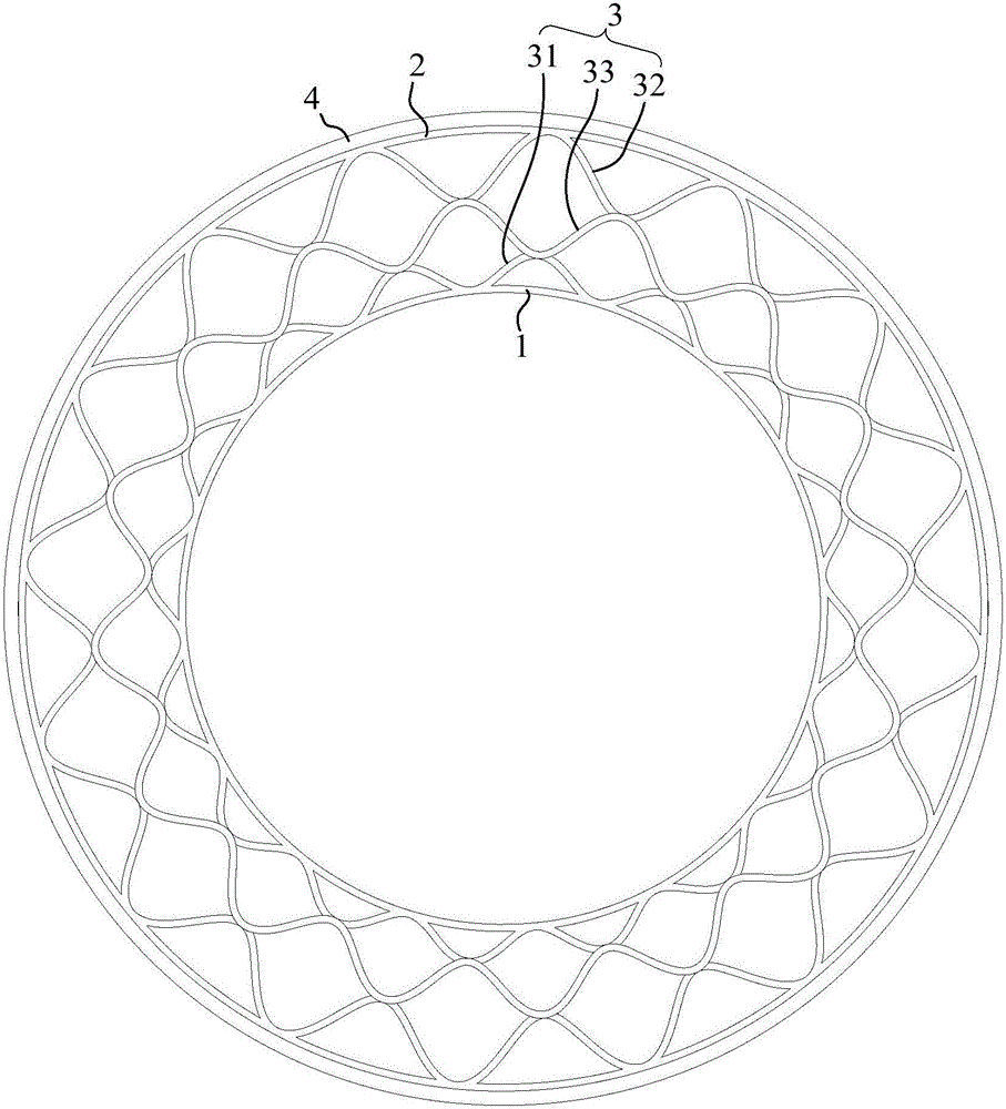
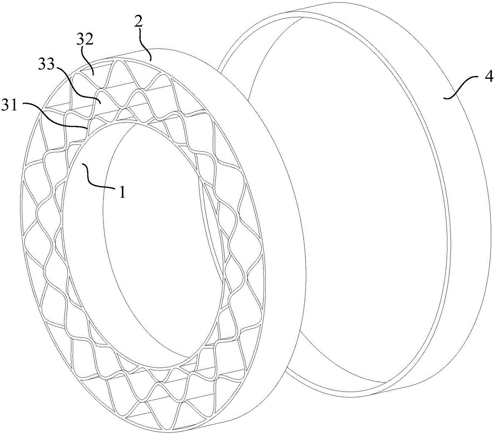
[0018] The air-free tire that the present invention proposes, please refer to Figure 1 to Figure 3 , in one embodiment, the non-pneumatic tire includes an annular inner ring part 1, an annular outer ring part 2 sleeved on the periphery of the inner ring part 1, and a support part between the inner ring part 1 and the outer ring part 2 3. The support part 3 includes a plurality of arched inner supports 31 arranged on the outer peripheral surface of the inner ring part 1, an outer support part 32 arranged on the inner peripheral surface of the outer ring part 2, and an inner support part 31 and an outer support part 32. Between the intermediate support 33. The outer...


PUM


Abstract

The invention discloses a non-pneumatic tyre. The non-pneumatic tyre comprises an annular inner ring part, an annular outer ring part and a supporting part, wherein the outer ring part is arranged on the periphery of the inner ring part in a sleeving manner, and the supporting part is arranged between the inner ring part and the outer ring part; the supporting part comprises a plurality of vaulted inner supporting components, outer supporting components and middle supporting components, wherein the vaulted inner supporting components are arranged on the periphery surface of the inner ring part, and the middle supporting components are positioned between the inner supporting components and the outer supporting components; the outer supporting components and the middle supporting components extend in the circumferential direction in a wavy manner, and the inner ring part is surrounded by the outer supporting components and the middle supporting components; the wave crest of each outer supporting component is connected with the inner periphery surface of the corresponding outer ring part, and the wave trough of each outer supporting component is connected with the wave crest of the corresponding adjacent middle supporting component; in two adjacent middle supporting components, the wave trough of each middle supporting component adjacent to the outer ring part is connected with the wave crest of the corresponding middle supporting component adjacent to the inner ring part; two ends of the inner supporting components are connected with the periphery surface of the inner ring part, and the top of each inner supporting component is connected with the wave trough of the corresponding adjacent middle supporting component. The non-pneumatic tyre disclosed by the invention is good in buffering effect and high in torsional rigidity.

Description

technical field [0001] The invention relates to the technical field of tires, in particular to a non-pneumatic tire. Background technique [0002] Pneumatic tires are filled with air with a certain pressure. In use, the deformation of the tire is mainly used to carry the load and buffer the impact. However, such inflated tires are likely to have the risk of air leakage, and if sudden air leakage such as punctures occurs in the pneumatic tires running at high speed, it is also easy to cause traffic accidents. [0003] Thus, in an existing air-free tire, its spoke plate extends radially along the tire, so that when the tire is in contact with the ground, the length direction of the main load-bearing spoke plate tends to be perpendicular to the road surface, so that the spoke plate The spoke plate can only carry or cushion the load by stretching or compressing in the radial direction of the tire, and transmit torque through the bending deformation of the spoke plate. For tire...

Claims


Application Information

Patent Timeline
Patent Type & Authority Applications(China)
IPC IPC(8): B60C7/10
Inventor 张裕盈张永汉林裕玲
Owner 张永汉
Why Eureka
Try Eureka