self-locking connector

An automatic locking and joint seat technology, which is applied in fluid pressure actuating devices, winding strips, thin material handling, etc., can solve problems such as lifting difficulties, personal injuries, and damaged products, and achieves easy quality assurance and convenient production , the effect of simplifying the design

Active Publication Date: 2017-06-09
四川省自贡市海川实业有限公司
View PDF7 Cites 0 Cited by
  • Summary
  • Abstract
  • Description
  • Claims
  • Application Information

AI Technical Summary

Problems solved by technology

The laminating roller 1 plus the film weighs more than 1 ton. Since the pressure roller 13 is above the laminating roller 1, it is difficult to lift and it is easy to pollute, damage the product and cause personal injury.

Method used


Image

  • self-locking connector
  • self-locking connector
  • self-locking connector

Examples


Embodiment Construction

[0038] In order to make the technical means, creative features, goals and effects achieved by the present invention easy to understand, the present invention will be further described below in conjunction with specific illustrations.

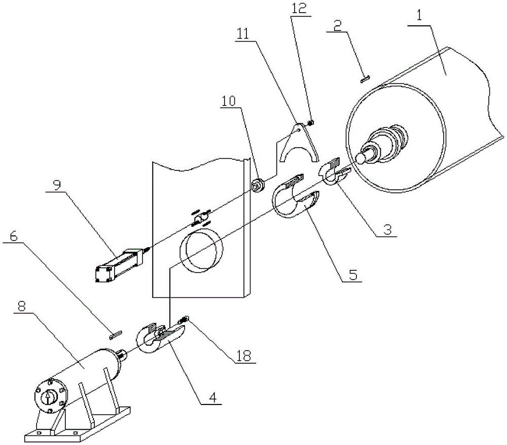
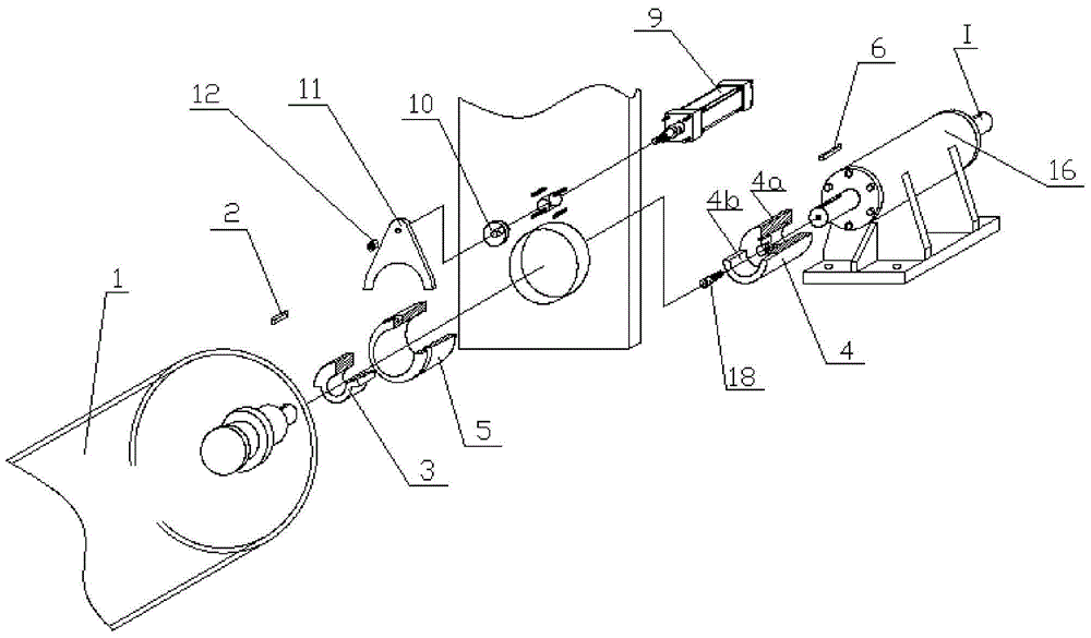
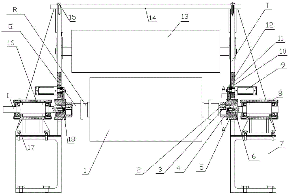
[0039] see Figures 1 to 11 , an automatic locking joint, including a machine base 7, a sliding sleeve 5, a rotating joint seat 4, a film-coated roller joint 3 and a fork mechanism.

[0040] The machine base 7 is provided with a side plate T, and the side plate T is respectively provided with a sliding sleeve installation hole and a piston rod action hole, and the piston rod action hole is located above the sliding sleeve installation hole.

[0041] The sliding sleeve 5 is installed at the installation hole of the sliding sleeve, and the outer surface of the sliding sleeve 5 is provided with a ring groove near the side of the coating roller.

[0042] The rotating joint seat 4 has a rotating shaft connection structure 4a and a coating roller joi...


PUM


Abstract

The invention discloses an automatic locking joint, which comprises: a machine base, on which a side plate is arranged, and a sliding sleeve installation hole and a piston rod action hole are arranged on the side plate; The outer surface of the sleeve is provided with a ring groove; the rotating joint seat has a shaft connection structure and a film-coated roller joint installation structure, and the rotating joint seat is installed in the sliding sleeve; the film-coated roller joint has a shaft hole and a film-coated roller joint connection key surface , the coating roller joint is installed at the installation structure of the coating roller joint, and the shaft hole is used to connect the joint at the end of the coating roller; the shift fork mechanism has a shift fork, a limit washer and a push cylinder, and the push cylinder is arranged on the piston The rod action hole is away from the side of the coating roller, the piston rod of the push cylinder passes through the piston rod action hole, and is connected with the limit washer. The shift fork is set at the end of the push cylinder piston rod, and the fork of the shift fork is embedded in the sliding sleeve in the ring groove. The invention has the advantages of convenient clamping, less required movement, simplified design, convenient production, reliable operation and wide adaptability.

Description

technical field [0001] The invention relates to an automatic locking joint. Background technique [0002] Laminating roller 1 realizes rotary motion under motor drive, and plastic film roll is pasted on the laminating roller, because process needs, pressure roller 13 pressurizes film. Laminating roller 1 adds that film has more than 1 ton, because pressure roller 13 is on laminating roller 1, it is difficult to lift and easy to pollute, damage product and cause personal injury. In view of the above reasons, it was decided to implement automatic loading and unloading of the lamination roller 1. The key to automatic loading and unloading lies in simple and reasonable clamping. Therefore, how to provide an automatic locking joint to meet the clamping requirements has become an urgent problem to be solved. Contents of the invention [0003] The object of the present invention is to solve the above problems and provide an automatic locking joint that facilitates automatic load...

Claims


Application Information

Patent Timeline
Patent Type & Authority Patents(China)
IPC IPC(8): B65H19/30F15B15/14
Inventor 刘建文
Owner 四川省自贡市海川实业有限公司
Why Eureka
Try Eureka