Test bench for testing working conditions of motor under different temperature environments

A technology of temperature environment and test environment, which is applied in the direction of motor generator testing, measuring device casing, etc., can solve the problem that the detection means cannot perfectly test the state of brushless motors, etc., and achieve fast detection speed, simple structure, and improved sealing effect Effect

Inactive Publication Date: 2015-12-02
NINGBO TUOPU INTELLIGENT BRAKE SYST
View PDF7 Cites 10 Cited by
  • Summary
  • Abstract
  • Description
  • Claims
  • Application Information

AI Technical Summary

Problems solved by technology

[0003] The performance of the brushless motor needs to be tested after the production is completed. Ordinary detection methods cannot perfectly test the working status of the brushless motor in different temperature environments. In order to achieve the best test results, a new test bench is designed. Necessary

Method used


Image

  • Test bench for testing working conditions of motor under different temperature environments
  • Test bench for testing working conditions of motor under different temperature environments
  • Test bench for testing working conditions of motor under different temperature environments

Examples


Embodiment 1

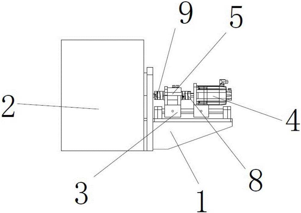
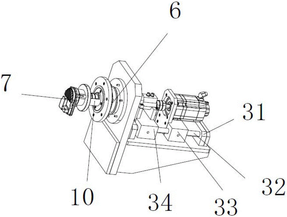
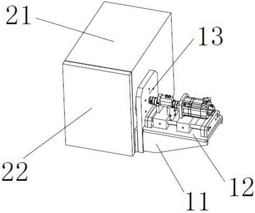
[0027] When it is necessary to use the device to test the brushless motor, first open the lid 22 of the test environment control box 2, and then connect the main shaft of the test motor 7 to the main shaft of the sealing box sealing assembly 6 through the third coupling 10, Rotate the sealing box closing assembly 6, so that the sealing box closing assembly 6 is close to the inner wall of the test environment control box 2, improve the sealing performance of the entire test environment control box 2, then close the box cover 22, and simultaneously control the test environment through the test environment control box 2 The internal temperature of the box 2, when the temperature reaches the test temperature, start the servo motor 4, the main shaft of the test environment control box 2 drives the main shaft of the test motor 7 to rotate, while the test motor 7 rotates, the torque sensor 5 will collect the motion state of the test motor 7, The data is transmitted to the computer thr...

Embodiment 2

[0030] When the whole test bench needs to be maintained, at first open the case cover 22 of the test environment control box 2, the third shaft coupling 10 and the sealing box sealing assembly 6 are disassembled, and then the fixed bench 1 is removed from the test environment control box 2 side The wall is disassembled, and then the mounting table 3 is disassembled from the fixed table 1, and the worker can carry out the test environment control box 2, the mounting table 3, the fixed table 1, and the torque sensor 5 and the servo motor 4 on the mounting table 3. For detection and maintenance, when the torque sensor 5 or the servo motor 4 needs to be replaced, first remove the first coupling 8, so that the servo motor 4 and the torque sensor 5 are separated, and then put the servo motor 4 and the torque sensor 5 on the installation platform 3 The two ends are translated to make it easy to replace the servo motor 4 and the torque sensor 5, and then replace the servo motor 4 insta...


PUM


Abstract

The invention relates to a test bench for testing the working conditions of a motor under different temperature environments. One side of a test environment adjustment and control box (2) is provided with a fixing rack (1); the fixing rack (1) is provided with an installation stage (3); the installation stage (3) is provided with a servo motor (4); the main shaft of the servo motor (4) faces the test environment adjustment and control box (2) and is connected with one end of the main shaft of a torque sensor (5); the other end of the main shaft of the torque sensor (5) is connected with one end of the main shaft of a seal box sealing assembly (6) installed at the inner wall of the test environment adjustment and control box (2); and the other end of the main shaft of the seal box sealing assembly (6) is connected with the main shaft of a test motor (7). The test bench of the invention has the advantages of simple structure, convenient operation and high detection speed, and can detect the working conditions of the motor under different temperatures.

Description

technical field [0001] The invention relates to the technical field of motor test benches, in particular to a test bench for testing motors working in different temperature environments. Background technique [0002] The BLDC motor is a brushless motor, also known as a DC permanent magnet motor, or a permanent magnet synchronous motor, which uses a motor controller to achieve commutation through electronic control distribution. It is an advanced electronic drive motor, which not only has a series of advantages of simple structure, reliable operation and convenient maintenance of AC motor, but also has many advantages of high operating efficiency, no excitation loss and good speed regulation performance of DC motor. [0003] After the production of the brushless motor is completed, its performance needs to be tested. Ordinary testing methods cannot perfectly test the working status of the brushless motor in different temperature environments. In order to achieve the best test...

Claims


Application Information

Patent Timeline
Patent Type & Authority Applications(China)
IPC IPC(8): G01R1/04G01R31/34
Inventor 蒋开洪盛文文
Owner NINGBO TUOPU INTELLIGENT BRAKE SYST
Why Eureka
Try Eureka